Multi-beam medium column lens antenna

A technology of lens antenna and dielectric column, which is applied in the direction of antenna, antenna array, waveguide horn, etc., can solve the problems of complex processing and high cost, and achieve the effect of large scanning range, low cost and high gain

Inactive Publication Date: 2011-09-07
ZHEJIANG UNIV
View PDF8 Cites 15 Cited by
  • Summary
  • Abstract
  • Description
  • Claims
  • Application Information

AI Technical Summary

Problems solved by technology

The authorized announcement number is CN101098050B, which is called the patent document of radio wave lens antenna device, and the patent document of application number 200480008809.3, which is also called radio wave lens antenna device, both use spherical Lunberg lenses, but the volume problem and processing accuracy cannot be ignored. The problem
The application announcement number CN101699659A is called a patent document for a lens antenna, and the publication number is CN101587990A called a broadband cylindrical lens antenna based on artificial electromagnetic materials. Both of them use cylindrical lens antennas, but their lens materials are artificially synthesized. The processing is extremely complicated and the cost is high

Method used


Image

  • Multi-beam medium column lens antenna
  • Multi-beam medium column lens antenna
  • Multi-beam medium column lens antenna

Examples


Embodiment Construction

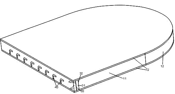
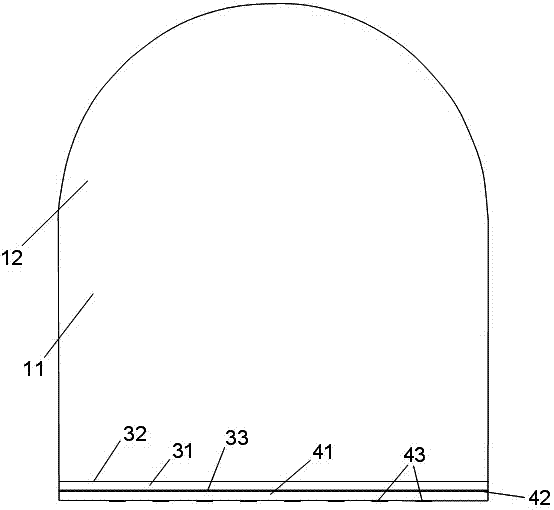
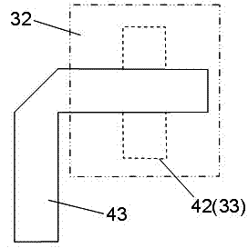
[0018] Such as figure 1 , 2 As shown, a multi-beam dielectric cylindrical lens antenna includes a dielectric cylindrical lens 1, a metal plate waveguide 2, an antenna part 3 and a feed source part 4; the dielectric cylindrical lens 1 includes a rectangular medium 11 and a semicircular medium 12, and the rectangular medium 11 The width is equal to the diameter of the semicircular medium 12, the height of the rectangular medium 11 is equal to that of the semicircular medium 12, the metal plate waveguide 2 is provided with two metal plates up and down, and the shape of the metal plate of the metal plate waveguide 2 is the same as that of the dielectric cylindrical lens 1 , the antenna part 3 includes a dielectric substrate 31 in the middle, a patch antenna array 32 on one side of the dielectric substrate 31 and a coupling slot array 33 on the other side of the dielectric substrate 31, the patch antenna array 32 is composed of 8 rectangular patches in parallel, The coupling slot ...


PUM


Abstract

The invention discloses a multi-beam medium column lens antenna, comprising a dielectric column lens, a metal plate waveguide, an antenna part and a feed source part, wherein the metal plate waveguide is provided with an upper metal plate and a lower metal plate; the antenna part comprises a dielectric substrate in the middle part, a patch antenna array at one side of the dielectric substrate and a coupled gap array at the other side of the dielectric substrate; the patch antenna array is formed by eight rectangle patches in parallel; the feed source part comprises a dielectric substrate in the middle part, a coupled gap array at a side surface inside the dielectric substrate and an L-shaped micro-strip feeder line array at a side surface outside the dielectric substrate; the coupled gap array of the feed source part and the coupled gap array of the antenna part are of the same shape and fitted mutually; the L-shaped micro-strip feeder line array is formed by eight paths of L-shaped micro-strip feeder lines; and one path of the L-shaped micro-strip feeder lines in the L-shaped micro-strip feeder line array corresponds to a rectangle slot of each coupled gap array respectively. The antenna has the characteristics that the structure is simple, the processing is easy, the weight is light, the scanning range is wide, and the cost is low and the like.

Description

technical field [0001] The invention relates to a lens antenna, in particular to a multi-beam dielectric cylindrical lens antenna. Background technique [0002] With the rapid development of microwave technology, the core supporting role of communication in military and civilian applications has become more and more obvious, and now the antenna has become the most important link restricting the development of communication. Regardless of whether it is for military or civilian use, information is an important component, and maintaining smooth communication anytime and anywhere has become a necessary requirement. [0003] The lens antenna is one of the most commonly used microwave antennas. Compared with the reflector antenna, the lens is unobstructed and can be scanned more conveniently, and it is easy to achieve scanning with a larger angle range and sufficient gain flatness. In the application of multi-mode common aperture antenna and multi-beam antenna, the lens is more a...

Claims


Application Information

Patent Timeline
Patent Type & Authority Applications(China)
IPC IPC(8): H01Q1/38H01Q13/02H01Q13/08H01Q19/06H01Q15/08H01Q21/00
Inventor 吴锡东杨楠朱道虹王中元吴慧娴周金芳
Owner ZHEJIANG UNIV
Why Eureka
Try Eureka