Heart assist apparatus

A technology of cardiac assistance and equipment, applied in the direction of mechanical equipment, circulatory assistance devices, prostheses, etc., can solve the problems of changing the working characteristics, wear, and inappropriateness of ventricular assist devices

Inactive Publication Date: 2011-09-07
CALON CARDIO TECH
View PDF5 Cites 12 Cited by
  • Summary
  • Abstract
  • Description
  • Claims
  • Application Information

AI Technical Summary

Problems solved by technology

Conventional bearings are not suitable as they eventually wear out an

Method used


Image

  • Heart assist apparatus
  • Heart assist apparatus
  • Heart assist apparatus

Examples


Embodiment Construction

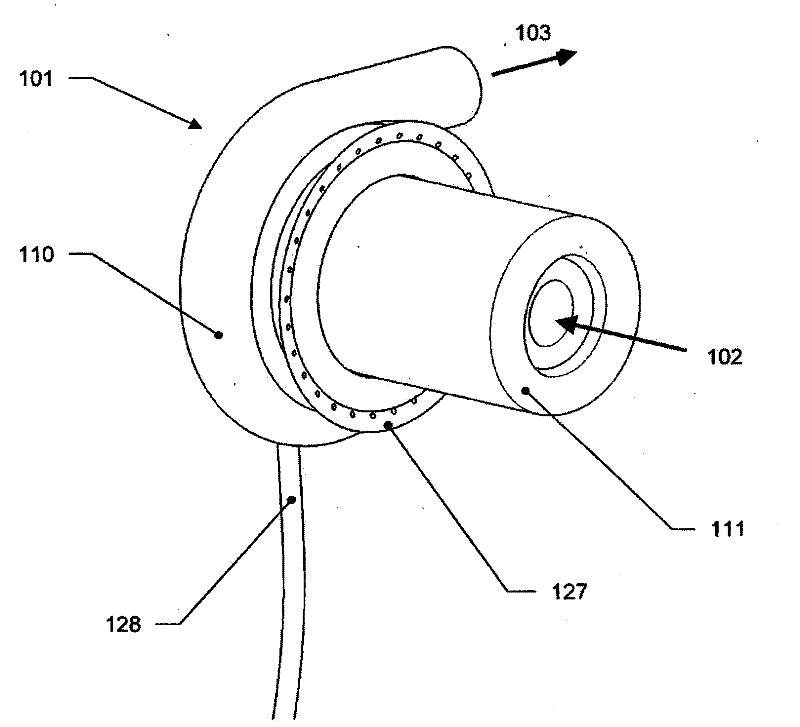
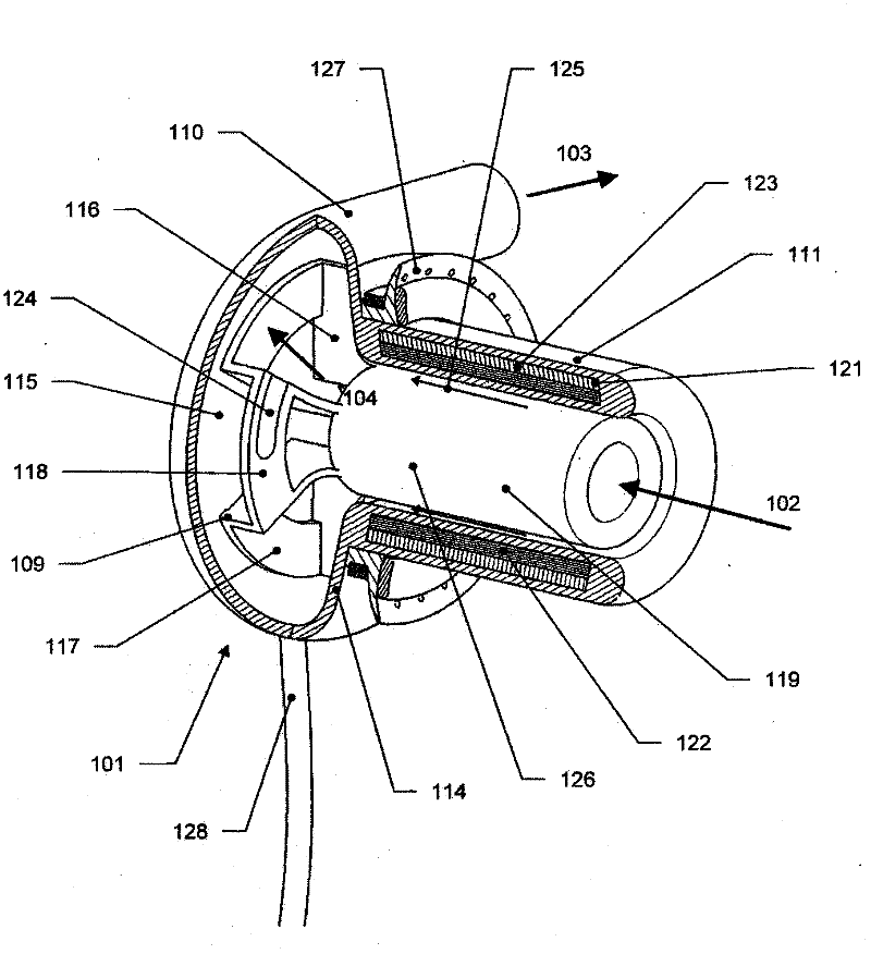
[0044] Figure 1 to Figure 6 , wherein like parts are marked with like reference numerals, shows a first embodiment of a ventricular assist device according to the present invention. The ventricular assist device VAD comprises a pump chamber 101 with a blood inlet 102 and a blood outlet 103 . A main blood flow channel 104 is defined between the inlet 102 and the outlet 103 .

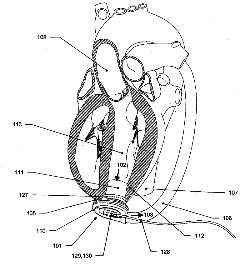
[0045] When implanted (see figure 2 ), the pump chamber 101 is located outside the heart, on the apex 105 of the ventricle, its outlet 103 is connected with an outflow cannula 106 which in turn is grafted to the descending aorta 107 . It is also possible to graft the outflow cannula 106 to the ascending aorta 108 (not shown in the figure). The pump chamber 101 includes an impeller 109 which is preferably radial or mixed flow and a volute 110 which assists in the conversion of kinetic energy thereby increasing efficiency.

[0046] The positioning of the pump chamber 101 outside the heart allows it to b...


PUM


Abstract

The apparatus is a ventricular assist device comprising: a pump with a housing having therein radial a impeller, and a rotor for driving the impeller, both the rotor and the impeller being hydrodynamically suspended within the housing in us, the pump further including a stator for driving the rotor; an inlet cannula section arranged to extend from an internal part of the ventricle to straddle the wall of the ventricle, the stator being within the inlet cannula section to be located in the internal part of the ventricle; and an outlet for blood driven by the impeller such that the pump is a radial pump. Both the outlet and the impeller are arranged to reside outside of the heart.

Description

technical field [0001] The present invention relates to implantable cardiac assist devices, such as ventricular assist devices. Background technique [0002] Heart failure is a major global health problem, killing thousands of people every year. Until recently, the only way to treat advanced heart failure was a heart transplant or implantation of an artificial heart. Unfortunately, only a small fraction of the needs are met with donor hearts, and total artificial hearts have not yet gained widespread acceptance due to the technical difficulties associated with them. [0003] Ventricular assist devices (VADs) have gradually gained acceptance over the past three decades, primarily as bridges to implanted devices. Ventricular assist devices are implanted chronically and work with a diseased heart to increase the output of the heart and keep the patient alive and / or give a better quality of life while awaiting transplantation. The use of these devices has produced unexpected ...

Claims


Application Information

Patent Timeline
IPC IPC(8): A61M1/10F04D29/22
CPCA61M2001/125A61M2001/1017A61M1/101A61M2001/122A61M2001/1015A61M60/824A61M60/422A61M60/148A61M60/863A61M60/178A61M60/806A61M60/226A61M60/814A61M60/221
Inventor 格雷厄姆·福斯特
Owner CALON CARDIO TECH
Why Eureka
Try Eureka