
Cylindrical filter press

A filter press and cartridge type technology, applied in the field of filter presses, can solve the problems of unfavorable high-efficiency production, small space for effective use of filter press, troublesome filter plate cleaning, etc.

Inactive Publication Date: 2011-09-14
张家港市轻工设备厂有限公司
View PDF2 Cites 4 Cited by
  • Summary
  • Abstract
  • Description
  • Claims
  • Application Information

AI Technical Summary

Problems solved by technology

[0002]The filter press currently used is generally a plate and frame filter press, which includes a filter frame, a filter plate and a beam, etc. The plates are arranged and slidably installed on the beam, and the end faces of the filter plates are provided with grooves, and the grooves between two adjacent filter plates form a filter chamber. The effective use of space is small, the floor area is relatively large, and the material for one-time filter press is less. At the same time, after the press filter is completed, the unloading is more complicated, and the cleaning of the filter plate after unloading is also very troublesome, which causes the efficiency of the filter press to drop. , which is not conducive to high-volume and efficient production

Method used


Image

  • Cylindrical filter press
  • Cylindrical filter press

Examples


Embodiment Construction

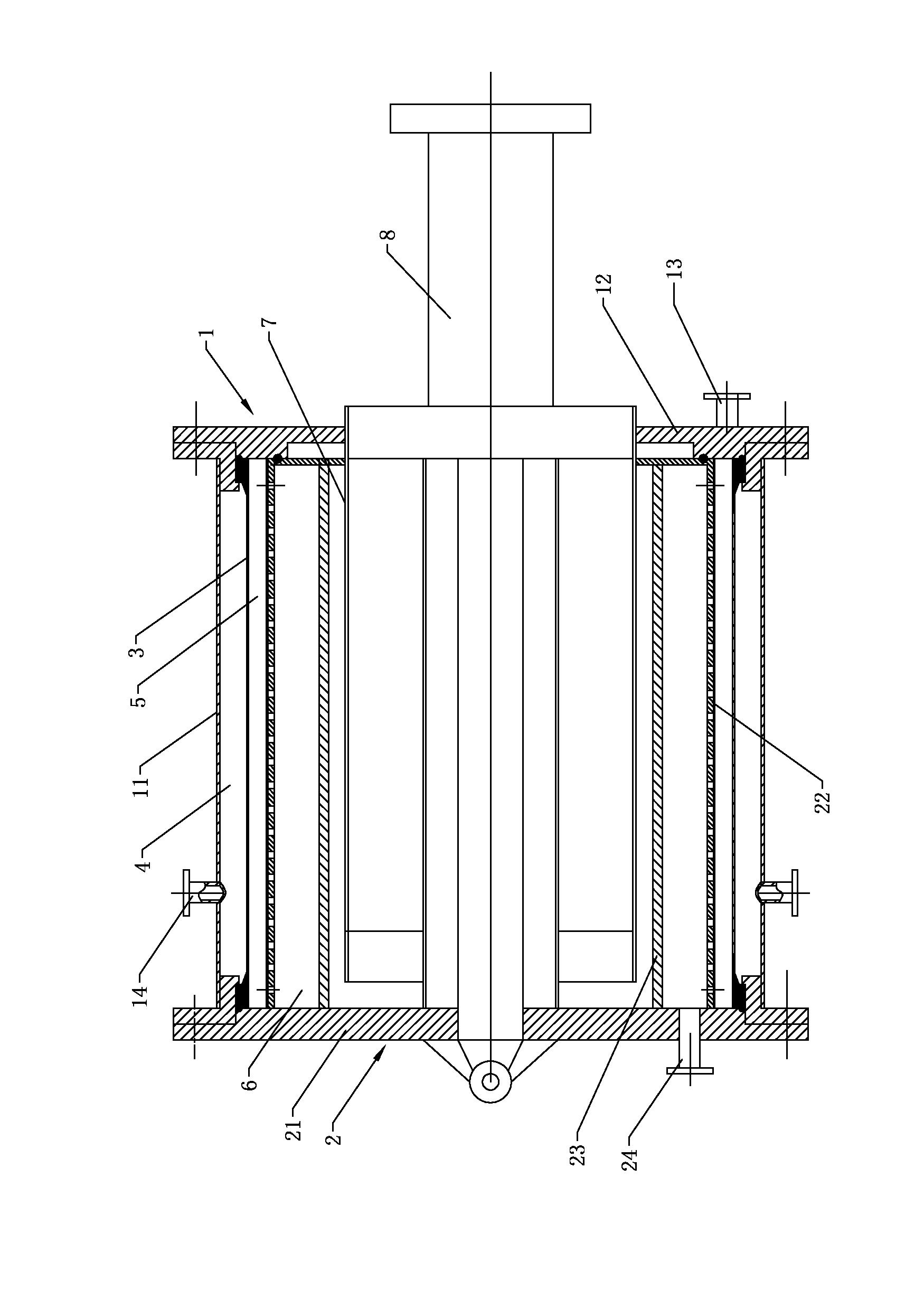
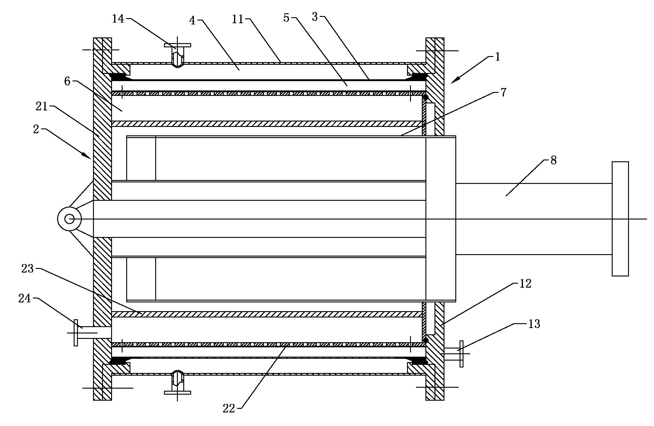
[0019] A cylindrical filter press, as shown in the accompanying drawings, is characterized in that it includes an outer cylinder 1 and an inner filter cylinder 2, and the inner filter cylinder 2 is axially slidably fitted in the inner cavity of the outer cylinder 1. The outer circumference of the cylinder wall of the inner filter cartridge 2 is provided with a filter hole and is wrapped with a filter cloth outside. The inner cavity wall of the outer cylinder 1 is provided with an expandable tension membrane 3, and the tension membrane 3 is connected to the inner filter cylinder 2. An annular airtight material filter cavity 5 is formed between the cylinder walls of the outer cylinder, and an annular airtight force application chamber 4 is formed between the tension film 3 and the cylinder wall of the outer cylinder 1, and the outer cylinder 1 is provided with a force application chamber 4 connected force medium inlet 14 and force medium outlet, and a feed port 13 communicated wi...


PUM


Abstract

The invention discloses a cylindrical filter press which comprises an outer cylinder and an inner filter cylinder, wherein the inner filter cylinder is sleeved in an inner cavity of the outer cylinder in an axial sliding manner, filter holes are arranged on the periphery of the cylinder wall of the inner filter cylinder and filter cloth is wrapped outside the inner filter cylinder, the inner cavity wall of the outer cylinder is provided with an expandable tensile membrane, an annularly-closed material filtering cavity is formed between the tensile membrane and the cylinder wall of the inner filter cylinder, an annularly-closed force applying cavity is formed between the tensile membrane and the cylinder wall of the outer cylinder, the outer cylinder is provided with a force applying medium inlet and a force applying medium outlet which are communicated with the force applying cavity, and a material inlet communicated with the material filtering cavity; and a filtrate collecting cavity is arranged in the inner filter cylinder, the inner filter cylinder is provided with a filtrate outlet communicated with the filtrate collecting cavity, and the inner filter cylinder is connected with a discharging power device used for driving the inner filter cylinder to discharge materials in an axial sliding manner. The filter press can be used for once filtering-pressing more materials with large filtering-pressing force and good filtering-pressing effect, and discharging the materials conveniently, and can be cleaned conveniently.

Description

technical field [0001] The invention relates to a filter press, in particular to a cylinder filter press which separates a solid-liquid mixture by press filtration. Background technique [0002] The filter press currently used is generally a plate-and-frame filter press, which includes a filter frame, a filter plate, and a beam, etc. Type, the groove shape between two adjacent filter plates forms a filter cavity, such a plate and frame filter press has a large volume, the effective use of space for the entire filter press is small, and the floor space is relatively large. At the same time, after the filter press is completed, the unloading is more complicated, and the cleaning of the filter plate after unloading is also very troublesome, which causes the efficiency of the filter press to decrease, which is not conducive to high-efficiency mass production. Contents of the invention [0003] The technical problem to be solved by the present invention is: to provide a cylind...

Claims


Application Information

Patent Timeline
Patent Type & Authority Applications(China)
IPC IPC(8): B01D25/12
Inventor 茅志才王平
Owner 张家港市轻工设备厂有限公司
Learn More