Locating tool for frameworks/reinforced ribs of integrated composite-material wing structural member and application method of locating tool

A technology of composite materials and integral components, applied in the direction of workpiece clamping devices, manufacturing tools, etc., can solve problems such as poor position accuracy, uncontrollable position accuracy of skeleton or reinforcement, and failure to meet assembly coordination requirements, etc., to meet assembly coordination requirements , Improve the effect of assembly quality

Active Publication Date: 2011-09-14
BEIJING AERONAUTICAL MFG TECH RES INST
View PDF5 Cites 12 Cited by
  • Summary
  • Abstract
  • Description
  • Claims
  • Application Information

AI Technical Summary

Problems solved by technology

The disadvantage of the above positioning method is: the position accuracy of the skeleton or reinforcement is poor, and it still cannot meet the assembly coordination requirements between the composite airfoil integral component and other components
The reason is that because the skeleton or reinforced curing mold is not constrained, and because the skeleton or reinforced blank is soft during the high-temperature curing process, there will be sliding displacement bet

Method used


Image

  • Locating tool for frameworks/reinforced ribs of integrated composite-material wing structural member and application method of locating tool
  • Locating tool for frameworks/reinforced ribs of integrated composite-material wing structural member and application method of locating tool
  • Locating tool for frameworks/reinforced ribs of integrated composite-material wing structural member and application method of locating tool

Examples


Embodiment 1

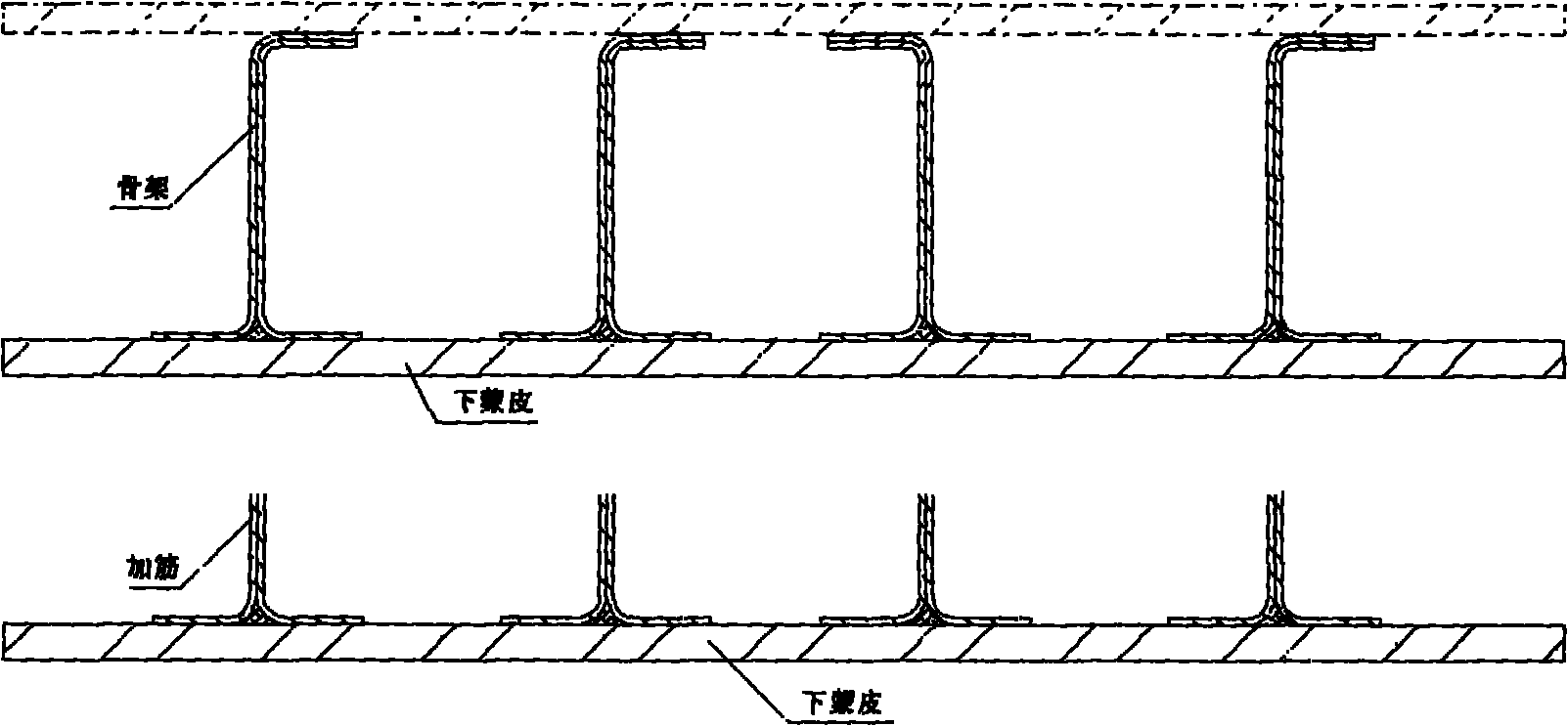
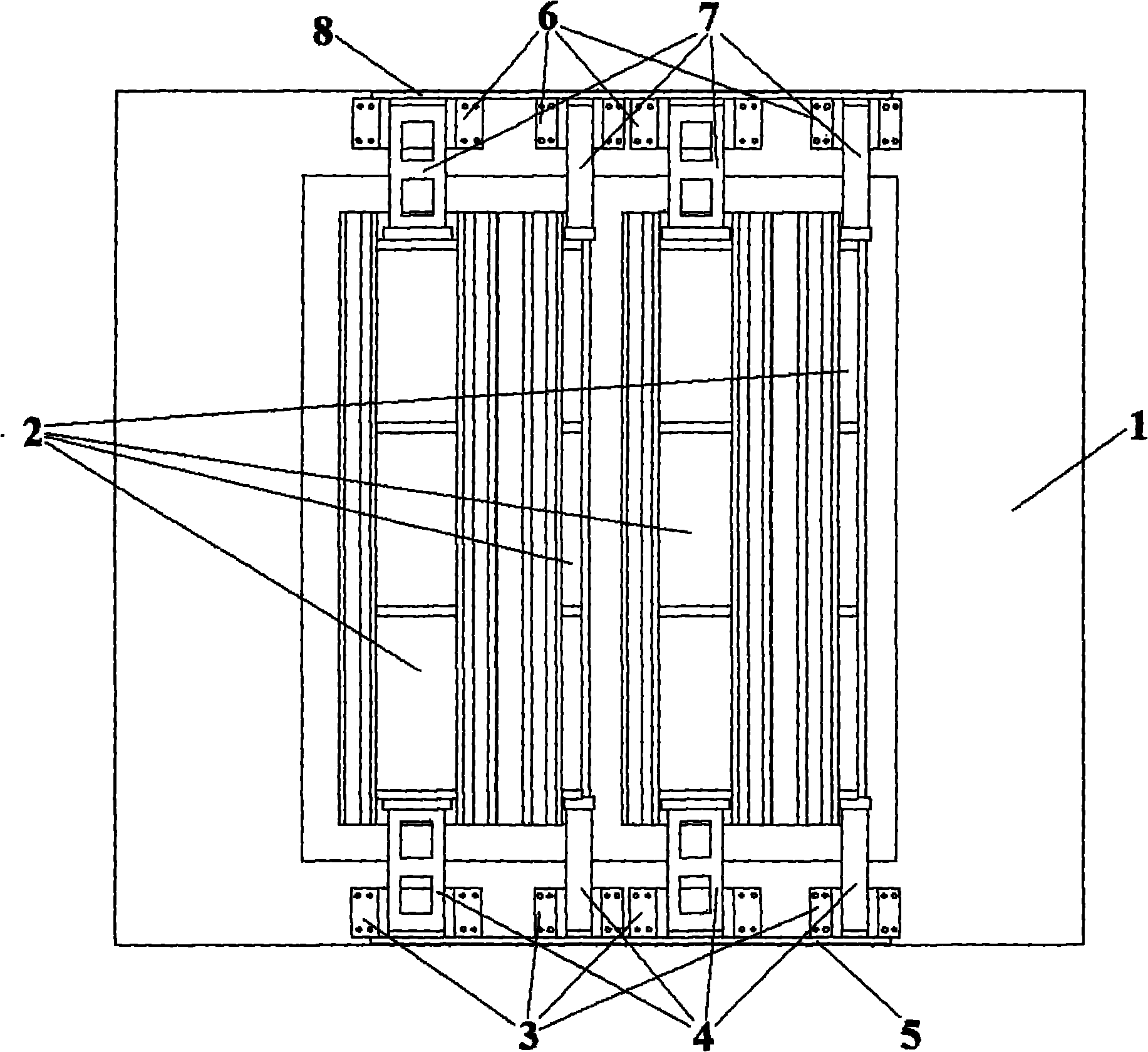
[0038] 1. A composite airfoil integral component with upper and lower skins, between which there are 5 composite materials that fit and connect with the upper and lower skins Type skeleton; positioning tooling for the skeleton of the overall component of the composite airfoil, including a skin mold made of steel and 5 skeleton curing molds, the shape of the skeleton curing mold is shape, the skeleton curing mold is located in outside of the frame, each The inner side of the type skeleton is a [shaped soft mold, a total of 5 soft molds; there is a skin profile on the skin mold, an uncured skin blank on the skin mold, and an uncured skin blank on the skin mold. There are 5 curing molds with skeleton blanks arranged; it consists of 5 wing root positioning devices and 5 wing tip positioning devices; the wing root positioning device is composed of 5 wing root positioning components and 1 wing root beam connection, each wing The root positioning assembly consists of 1 wing roo...

Embodiment 2

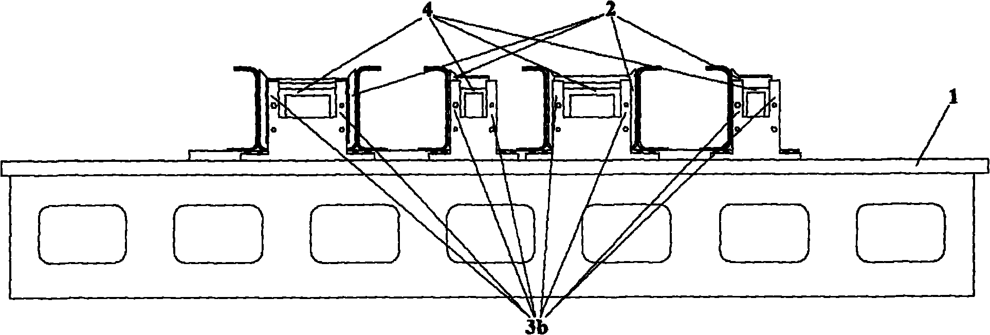
[0048] A composite airfoil integral panel with a lower skin, on the lower skin there are 10 composite material T-shaped reinforcements that are only connected to the lower skin; a positioning tool for the reinforcement of the composite material airfoil integral member , including 1 skin mold made of steel and 5 reinforcement curing molds. The cross-sectional shape of the reinforcement curing mold is rectangular. From the left, No. I reinforcement curing mold is located in the first T-shaped reinforcement 9 and the second T Type reinforcement 10, No. II reinforcement curing mold is located between the third T-type reinforcement 11 and the fourth T-type reinforcement 12, and No. III reinforcement curing mold is located between the fifth T-type reinforcement 13 and Between the sixth T-shaped reinforcement 14, No. IV reinforcement curing mold is located between the seventh T-shaped reinforcement 15 and the eighth T-shaped reinforcement 16, and No. V reinforcement curing mold is loc...


PUM


Abstract

The invention belongs to composite-material structure forming technologies, and relates to a locating tool for frameworks/reinforced ribs of an integrated composite-material wing structural member and an application method of the locating tool. The locating tool is characterized in that: at the two ends of longitudinal direction of skin-covering molds (1), framework/reinforced rib curing mold locating devices are respectively arranged on the skin-covering molds outside a skin-covering molded surface; and the application method is characterized by comprising the following steps of: installing a wing root locator (3) and a wing tip locator (6); assembling and connecting a wing root connecting segment (4), a wing tip connecting segment (7) and a framework/reinforced rib curing mold (2); locating the framework/reinforced rib curing mold (2); placing a soft mold; packaging in a vacuum bag; installing a wing root transverse beam (5) and a wing tip transverse beam (8); and disassembling pins and fixing bolts of the locators. By the locating tool and the application method, the positional precision of the frameworks/reinforced ribs of an integrated composite-material wall panel is ensured, the requirement of assembly and coordination between the integrated composite-material wing structural member and other structural members is met, and the assembly quality is improved.

Description

technical field [0001] The invention belongs to composite material structure molding technology, and relates to a positioning tool for the skeleton or reinforcement of an integral component of a composite airfoil and a method for using the same. Background technique [0002] After years of development, composite materials have been gradually applied to large-scale main load-bearing structures. see figure 1 , figure 1 The upper picture in the figure is a composite material airfoil integral component with upper and lower skins, and there is a composite material skeleton connected to the upper and lower skins between the upper and lower skins. figure 1 The figure below is a composite material airfoil integral member with a lower skin, and there are composite material reinforcements that are only connected to the lower skin on the lower skin. The extension direction of the skeleton or reinforcement is the longitudinal direction of the composite airfoil, that is, the span dire...

Claims


Application Information

Patent Timeline
IPC IPC(8): B25B11/00
Inventor 梁宪珠常海峰薛向晨张西伟
Owner BEIJING AERONAUTICAL MFG TECH RES INST
Why Eureka
Try Eureka