
Energy-saving high-efficiency servo drive paper box printing mechanism

A servo-driven, carton printing technology, applied to printing machines, rotary printing machines, printing, etc., can solve problems such as inability to reduce energy consumption, inability to achieve non-stop plate change, and inability to effectively improve work efficiency and machine utilization. , to achieve the effect of improving work efficiency and machine utilization

Active Publication Date: 2011-09-14
GUANGDONG DONGFANG PRECISION SCI & TECH CO LTD
View PDF5 Cites 13 Cited by
  • Summary
  • Abstract
  • Description
  • Claims
  • Application Information

AI Technical Summary

Problems solved by technology

The configuration of the printing units of general carton printing equipment will configure the number of printing units according to the number of printing colors required by the order. In carton processing, not all orders will require all printing units to participate in printing. When When a group of printing units or several groups of printing units do not participate in the printing work, this group of printing units only plays the role of conveying the cardboard. It is also necessary to drive all the printing plate rollers and inking anilox rollers to work together, which cannot reduce energy consumption. Since the printing plate rollers and inking anilox rollers are still working at this time, it is not possible to install the printing plate rollers that do not participate in printing. The new printing plate (that is, it cannot change the plate without stopping the machine), can not effectively improve the work efficiency and improve the utilization rate of the machine

Method used


Image

  • Energy-saving high-efficiency servo drive paper box printing mechanism
  • Energy-saving high-efficiency servo drive paper box printing mechanism
  • Energy-saving high-efficiency servo drive paper box printing mechanism

Examples


Embodiment Construction

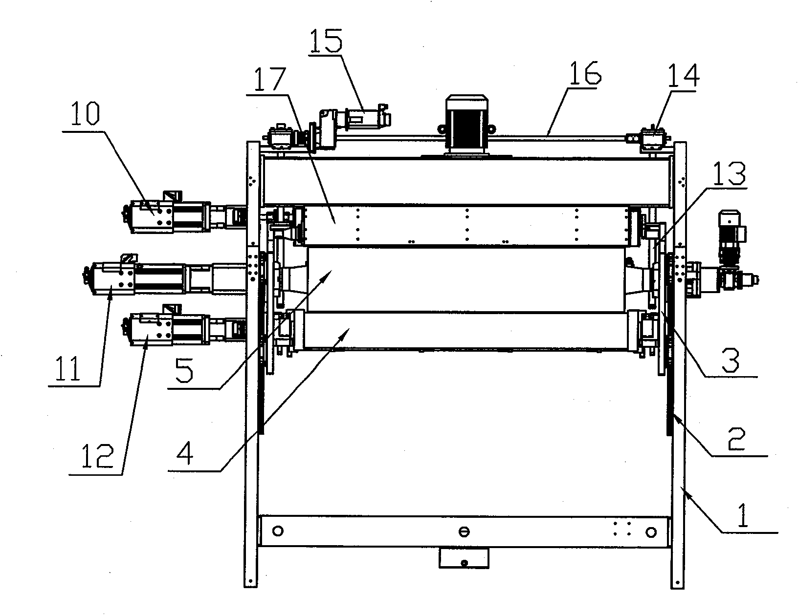
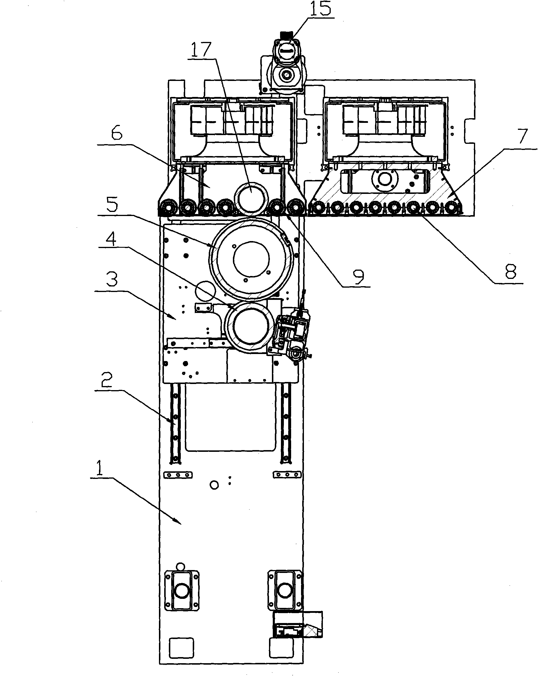
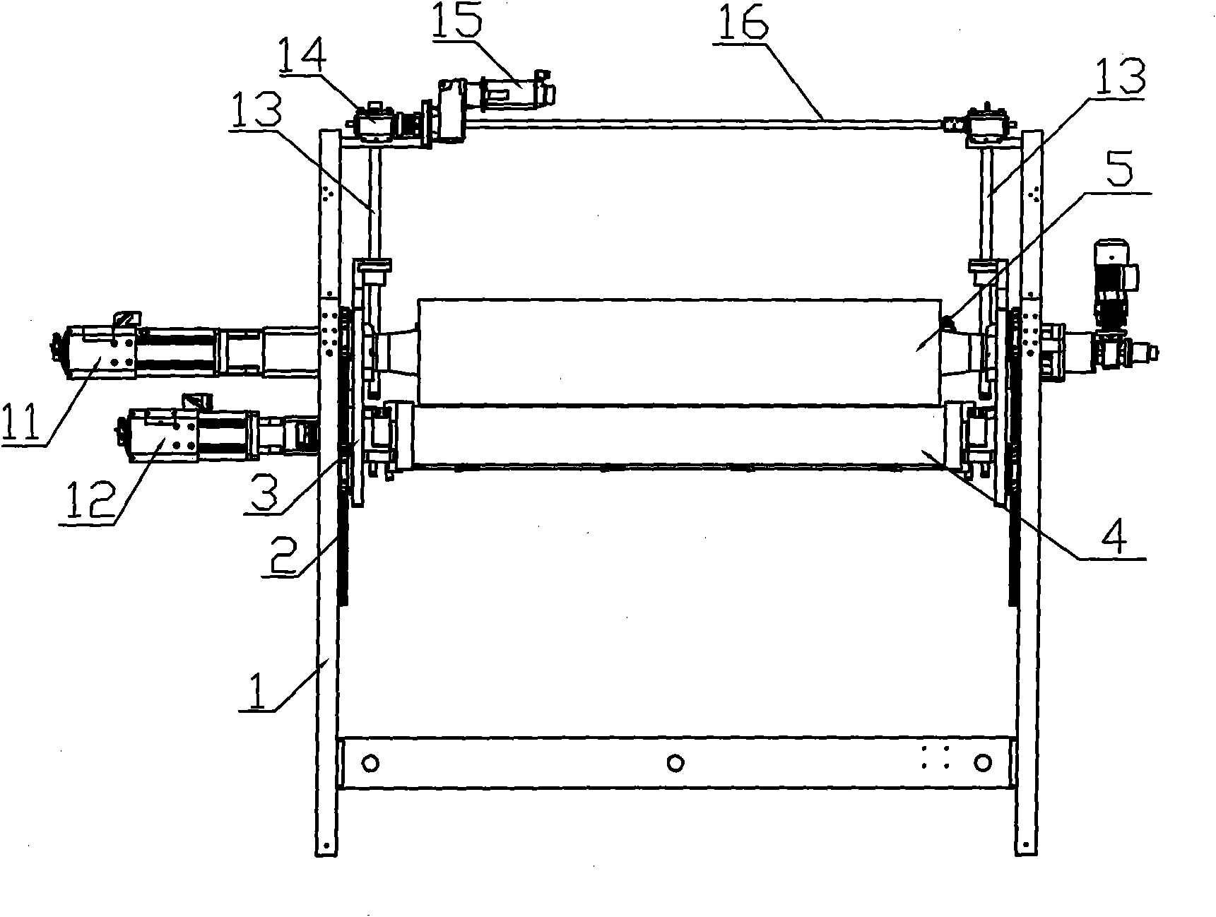
[0011] See figure 1 ~As shown in Figure 6, an energy-saving and high-efficiency servo-driven carton printing mechanism is composed of several printing units, each printing unit includes a frame with left and right side panels 1, linear guide rail pairs 2, left and right inner mounting panels 3, Inking anilox roller 4, printing plate roller 5, printing vacuum paper feeding transmission box 6, transitional vacuum paper feeding transmission box 7, paper feeding wheel shaft 8, paper feeding wheel 9, paper feeding transmission servo drive motor 10, printing plate roller servo drive Motor 11, inking anilox roller servo drive motor 12, screw mandrel 13, screw lifter 14, reduction motor 15, transmission shaft 16. The left and right inner mounting plates 3 are respectively installed on the left and right side plates 1 of the frame by sliding up and down through the linear guide pair 2; the printing plate roller 5 and the ink anilox roller 4 are respectively installed on the left and ri...


PUM


Abstract

The invention discloses an energy-saving high-efficiency servo drive paper box printing mechanism. The mechanism consists of a plurality of printing units, wherein the printing transfer and transition transfer of each group of printing unit are finished by a vacuum paper feeding transmission box; a printing plate roller for transferring printing ink to a paper board and an inking anilox roller are arranged on the two sides of a frame through a linear guide rail; a speed reducing motor synchronously drives screw rods on two sides through a spiral lifter to drive the printing plate roller and the inking anilox roller to lift up and down; and the vacuum paper feeding transmission box, the printing plate roller and the inking anilox roller are driven by a servo drive motor respectively. By the mechanism, the printing plate roller and the inking anilox roller of the printing unit which does not participate in printing stop operating during printing, and the paper board is continuously transferred by the vacuum paper feeding transmission box, so that the aim of saving energy is fulfilled, and the printing unit which does not participate in printing can be subjected to plate assembling, replacing and wiping operation during printing to fulfill the aims of improving work efficiency and a machine utilization rate.

Description

technical field [0001] The invention relates to the technical field of carton printing machinery, in particular to a servo-driven carton printing mechanism. Background technique [0002] The carton printing machine is to print the designed printing pattern on the cardboard, and then make it into carton packaging through forming and gluing. The carton printing machine is composed of multiple printing units. The traditional carton printing machine is driven by an ordinary motor to drive the gear transmission chain to drive multiple printing units. When the equipment is working, the gear transmission system of the printing unit is responsible for the printing of the unit In addition to the transmission, the movement must be transmitted to the next unit. The configuration of the printing units of general carton printing equipment will configure the number of printing units according to the number of printing colors required by the order. In carton processing, not all orders wil...

Claims


Application Information

Patent Timeline
IPC IPC(8): B41F13/004B41F13/008
Inventor 唐灼林
Owner GUANGDONG DONGFANG PRECISION SCI & TECH CO LTD
Learn More