Metal removing agent and metal removing filter
A metal removal and filter technology, applied in transportation and packaging, machines/engines, fat oil/fat refining, etc.
- Summary
- Abstract
- Description
- Claims
- Application Information
AI Technical Summary
Problems solved by technology
Method used
Image

Examples
no. 1 approach
[0024] The metal removing agent of the first embodiment of the present invention is described below.
[0025] The first embodiment describes a method of producing different types of metal removers such as evaluation samples E1 to E6 and comparative samples C1 and C2, and also describes the evaluation results of these samples as metal removers.
[0026] The metal removing agent of the first embodiment (such as evaluation samples E1 to E14) is composed of a resin containing anionic functional groups having a functional group density (or concentration) in the range of 2 to 25 mmol / ml.
[0027] First Embodiment Various types of evaluation samples E1-E14 and comparative samples C1-C6 were prepared as metal removing agents.
[0028] First, an evaluation sample E1 containing a sulfonic acid group as an anionic functional group was prepared by the method described below.
[0029] Fuming sulfuric acid (or olem) and dichloromethane at a concentration of 30 wt% (weight percent concentra...
no. 2 approach
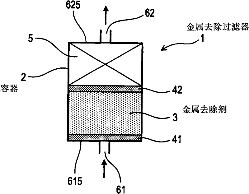
[0110] Refer to the attached figure 1 A metal removal filter according to a second embodiment of the present invention will be described.
[0111] figure 1 Shown is the structure of a metal-removing filter 1 with a metal-removing agent according to the second embodiment of the present invention.
[0112] Such as figure 1 As shown, the metal removal filter 1 has an approximately cylindrical container 2 and a metal removal agent 3 . Metal remover 3 is one of evaluation samples E1-E14 according to the first embodiment, which has a functional agent density (or concentration) in the range of 2-25 mmol / ml, capable of efficiently removing metal clusters contained in fuel.
[0113] The container 2 contains a metal remover 3 . The metal removal filter 1 further includes a fuel component 5 . Such as figure 1 As shown, the fuel component 5 is positioned in the container 2 such that the fuel component 5 and the metal remover 3 are stacked. That is, the space between the screen pair...
no. 3 approach
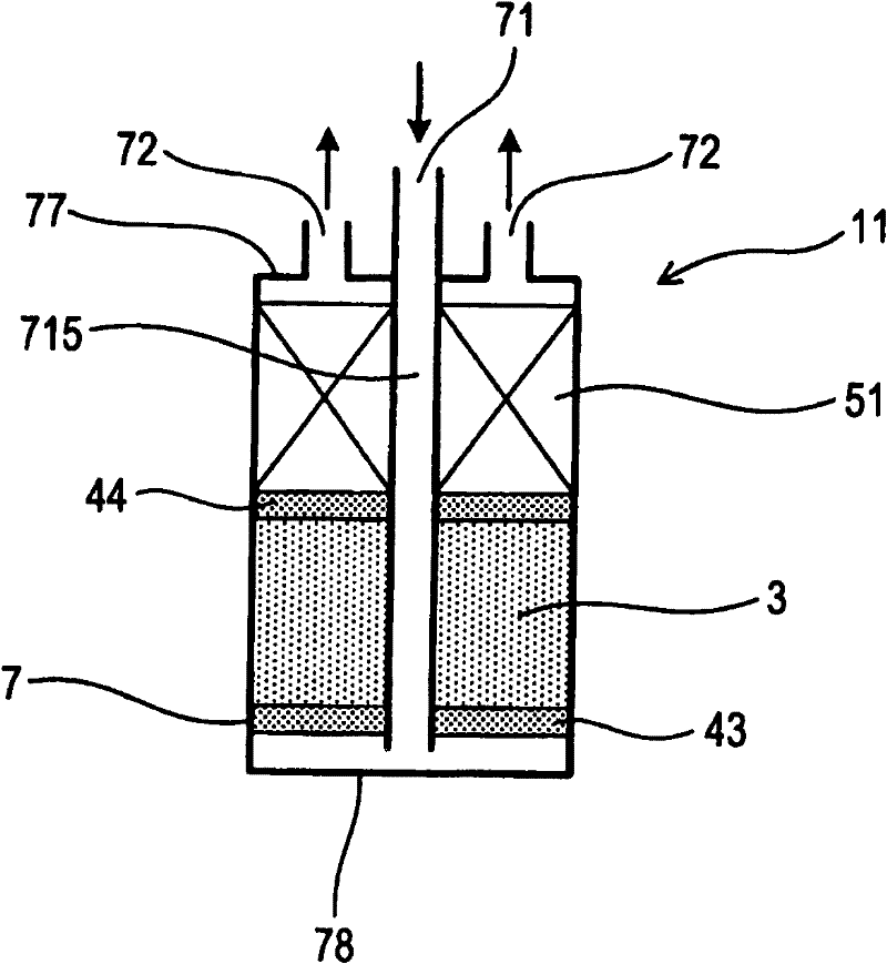
[0125] Refer to the attached figure 2 The metal removal filter 11 of the third embodiment of the present invention will be described.
[0126] figure 2 Shown is the structure of a metal removal filter 11 of a third embodiment of the present invention.
[0127] In the structure of the metal-removing filter 11 according to the third embodiment, fuel passes through the fuel passage 715, and flows from the top to the bottom of the metal-removing filter 11 in the vertical direction (or along the longitudinal direction of the metal-removing filter 11 in operation). .
[0128] Such as figure 2 shown, with figure 1 The structure of the metal-removing filter 1 according to the second embodiment shown is similar, and the metal-removing filter 11 according to the third embodiment includes a container 7 , a metal-removing agent 3 and a fuel member 51 . The container 7 accommodates the metal remover 3 and the fuel component 51 .
[0129] The container 7 has an approximately cylind...
PUM
| Property | Measurement | Unit |
|---|---|---|
| particle diameter | aaaaa | aaaaa |
| particle diameter | aaaaa | aaaaa |
| composition ratio | aaaaa | aaaaa |
Abstract
Description
Claims
Application Information
 - R&D
- Intellectual Property
- Life Sciences
- Materials
- Tech Scout
- Unparalleled Data Quality
- Higher Quality Content
- 60% Fewer Hallucinations
Browse by: Latest US Patents, China's latest patents, Technical Efficacy Thesaurus, Application Domain, Technology Topic, Popular Technical Reports.
© 2025 PatSnap. All rights reserved.Legal|Privacy policy|Modern Slavery Act Transparency Statement|Sitemap|About US| Contact US: help@patsnap.com