
Rigid transmission chain

A transmission chain and rigid technology, applied in the field of basic component chains, can solve problems such as inability to realize rigid transmission

Active Publication Date: 2011-09-14
ANHUI JINGYING MACHINERY MFG
View PDF6 Cites 2 Cited by
  • Summary
  • Abstract
  • Description
  • Claims
  • Application Information

AI Technical Summary

Problems solved by technology

Due to structural limitations, it cannot achieve rigid transmission

Method used


Image

  • Rigid transmission chain
  • Rigid transmission chain
  • Rigid transmission chain

Examples


Embodiment Construction

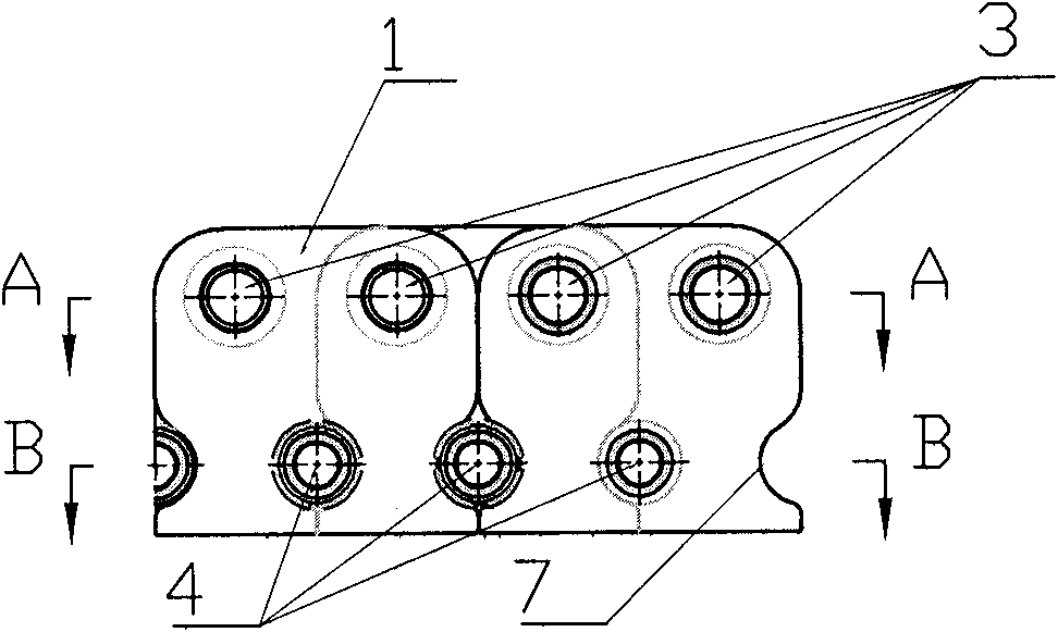
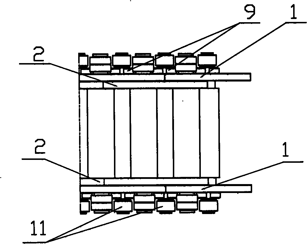
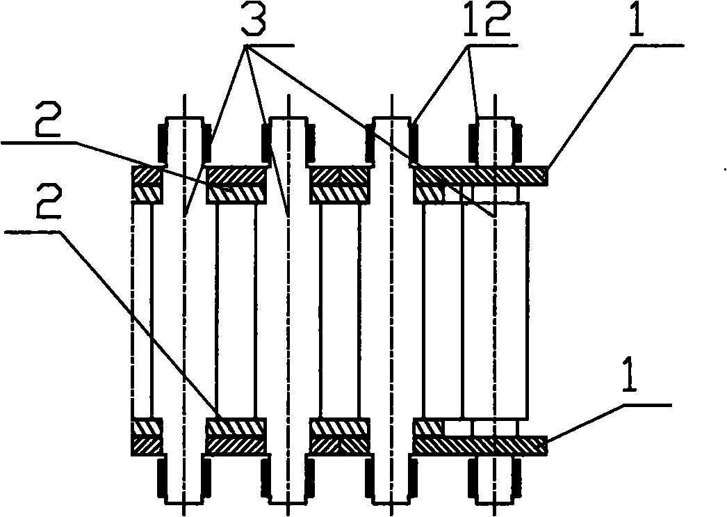
[0018] Such as figure 1 , figure 2 , image 3 , Figure 4 , Figure 5 , Figure 6 , Figure 7 As shown, the rigid transmission chain of the present invention includes multiple pairs of outer connecting plates 1, multiple pairs of inner connecting plates 2 arranged on the inner side of the outer connecting plates 1, and also includes a plurality of upper connecting shafts 3 and lower connecting shafts 4; The upper edge of the outer connecting plate 1 and the inner connecting plate 2 are symmetrically provided with the same rounded corners on both sides, the lower edge is straight and parallel to the upper edge, and the left and right edges are perpendicular to the lower edge. The outer connecting plate 1 and the inner connecting plate The upper end of the plate 2 is symmetrically provided with a left upper shaft hole 5 and a right upper shaft hole 6 with the same diameter, two semicircular holes 7 are symmetrically arranged on both sides of the lower end, and a lower shaf...


PUM


Abstract

The invention relates to a chain of basic component in chain transmission in mechanical transmission, in particular relates to a rigid transmission chain of a box-type structure, and in particular relates to the rigid transmission chain to realize pushing and pulling transmission force. The rigid transmission chain is composed of an outer connecting plate, an inner connecting plate, a lower connecting shaft, an upper connecting shaft, a sliding sleeve, a round nut, a bushing and a clamping ring; the inner connecting plate and the outer connecting plate are same in structure, and the staggering distance of the inner connecting plate and the outer connecting plate is a chain pitch; the inner connecting plate, the outer connecting plate and the connecting shaft form an inner box unit and an outer box unit; the end surface of the inner box unit and the end surface of the outer box unit are meshed, and can transmit force directly; and the inner box unit and the outer box unit are overlaid staggeredly, and the weight lifting up and down also can be finished. Compared with the traditional chain for which a loop is required to be closed, the chain provided by the invention can work in an open mode.

Description

1. Technical field [0001] The invention relates to a basic component chain of chain transmission in mechanical transmission, in particular to a rigid transmission chain. 2. Background technology [0002] The chain is a basic component widely used in mechanical transmission. The transmission chain adopts a closed structure, rotated by the driving sprocket, and drives the driven sprocket to rotate through the chain to realize the force transmission, which belongs to flexible transmission. Its structure generally includes a plurality of pairs of outer connecting plates and pairs of inner connecting plates, and the two are connected end to end through pin shafts. The outer connecting plate of the chain can do 360 ° rotation around the pin shaft on the inner connecting plate. Due to structural limitations, it cannot realize rigid transmission. 3. Contents of the invention [0003] The object of the present invention is to provide a rigid transmission chain, which can be trans...

Claims


Application Information

Patent Timeline
Patent Type & Authority Applications(China)
IPC IPC(8): F16G13/07F16G15/14
Inventor 程英程明陶磊方小山叶少白
Owner ANHUI JINGYING MACHINERY MFG
Learn More