Data transmission system, and monitoring system

A data transmission system and data area technology, applied in the field of data transmission, can solve problems such as cost increase, and achieve the effect of cost avoidance and high performance

Inactive Publication Date: 2011-09-14
LIXIL NITTAN
View PDF9 Cites 2 Cited by
  • Summary
  • Abstract
  • Description
  • Claims
  • Application Information

AI Technical Summary

Problems solved by technology

As a result, if a large-scale or high-performance fire protection system is used, all monitoring equipment (receivers) and terminal equipment must be replaced with new ones, which leads to a sharp increase in cost

Method used


Image

  • Data transmission system, and monitoring system
  • Data transmission system, and monitoring system
  • Data transmission system, and monitoring system

Examples


Embodiment Construction

[0032] Hereinafter, embodiments of the present invention will be described in detail with reference to the accompanying drawings.

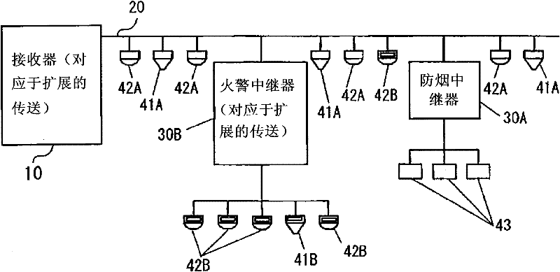
[0033] figure 1 An embodiment in which the present invention is applied to a fire monitoring system (also referred to in the art as a fire detection system and an alarm system) is shown as an example. The fire monitoring system according to this embodiment includes a receiver 10 (also referred to as a control panel or a fire alarm control panel in the art) as a control device or a monitoring device, and a repeater connected to the receiver 10 through a transmission path 20 30A and 30B (repeaters are also referred to as input-output modules in this field), and heat detectors 41A and 41B, smoke detectors 42A and 42B, and smoke dampers 43 are connected to the repeaters 30A and 30B, respectively. The heat detectors 41A and 41B and the smoke detectors 42A and 42B can be directly connected to the receiver 10 via the transmission path 20 without passin...


PUM


Abstract

In a data transmission system, a control device and a plurality of terminal devices are connected to each other through transmission path. A pulse signal composed of a data string is transmitted between the control device and the terminal devices. The data string has such a structure, including a mode region, an address storage region, a command region and a return data region which are disposed between a start bit and a stop bit; the stop bit could be replaced by an expanded bit which has a wave shape different from that of the stop bit; the mode region stores the the information for indicating that the data string is used for collecting the data or for controlling the terminal device; the address storage region stores the information for appointing the termial device; the command region stores the information for indicating the command content of the terminal device; and the return data region stores the return data. When the stop bit is replaced by the expanded bit, an expanding return data region is added followed by the expanded bit and the expaned return data is stored in the expanded return data region.

Description

[0001] The disclosure of Japanese Patent Application No. 2009-293905 filed on December 25, 2009 including specification, drawings and claims is hereby incorporated by reference. technical field [0002] The present invention relates to a data transmission system using a transmission path, and in particular, to a technique effectively applied to data transmission in a monitoring system such as a fire protection system, a security system, and the like. Background technique [0003] In a fire protection system provided with a monitoring device (receiver), which is installed in, for example, In buildings, factories, or events, it is used to monitor the occurrence of disasters such as fire by receiving detected signals from heat detectors, smoke detectors, and gas leak detectors. In such a configuration, the length of the transmission path may become extremely long. Preferably, the number of transmission lines for transmitting signals and the number of power supply lines for sup...

Claims


Application Information

Patent Timeline
Patent Type & Authority Applications(China)
IPC IPC(8): G08B17/11G08B25/00H04L69/40
CPCH04Q9/16G08B26/001G08B25/007G08B26/00H04L12/403
Inventor 石川康生高桥成政大内浩司鹈殿敏孝
Owner LIXIL NITTAN
Why Eureka
Try Eureka