
Fuse state monitoring protection device and protection method

A technology of protection devices and fuses, which is applied in the direction of automatic disconnection emergency protection devices, emergency protection circuit devices, measuring devices, etc., which can solve the problem that it is impossible to distinguish between fuse faults and line faults, and the fuse does not have a state monitoring function. , It is not easy to find specific fault points and other problems, so as to shorten the downtime, facilitate maintenance, and facilitate investigation

Inactive Publication Date: 2011-09-14
杭州银湖电气设备有限公司
View PDF1 Cites 10 Cited by
  • Summary
  • Abstract
  • Description
  • Claims
  • Application Information

AI Technical Summary

Problems solved by technology

[0004] The invention solves the disadvantage that the existing fuse does not have a state monitoring function, and it is not easy to find the specific fault point after the fuse fails, which brings difficulties to the investigation of the accident. It provides a fuse connected with the fuse that can monitor the working state of the fuse. Fuse state monitoring and protection device and protection method
[0005] The present invention also solves the disadvantage that the monitoring in the prior art is connected between the power supply and the load, and it is impossible to distinguish whether it is a fault of the fuse or a fault of the line after a fault occurs. Fuse state monitoring protection device and protection method for fuse working state

Method used


Image

  • Fuse state monitoring protection device and protection method
  • Fuse state monitoring protection device and protection method
  • Fuse state monitoring protection device and protection method

Examples


Embodiment

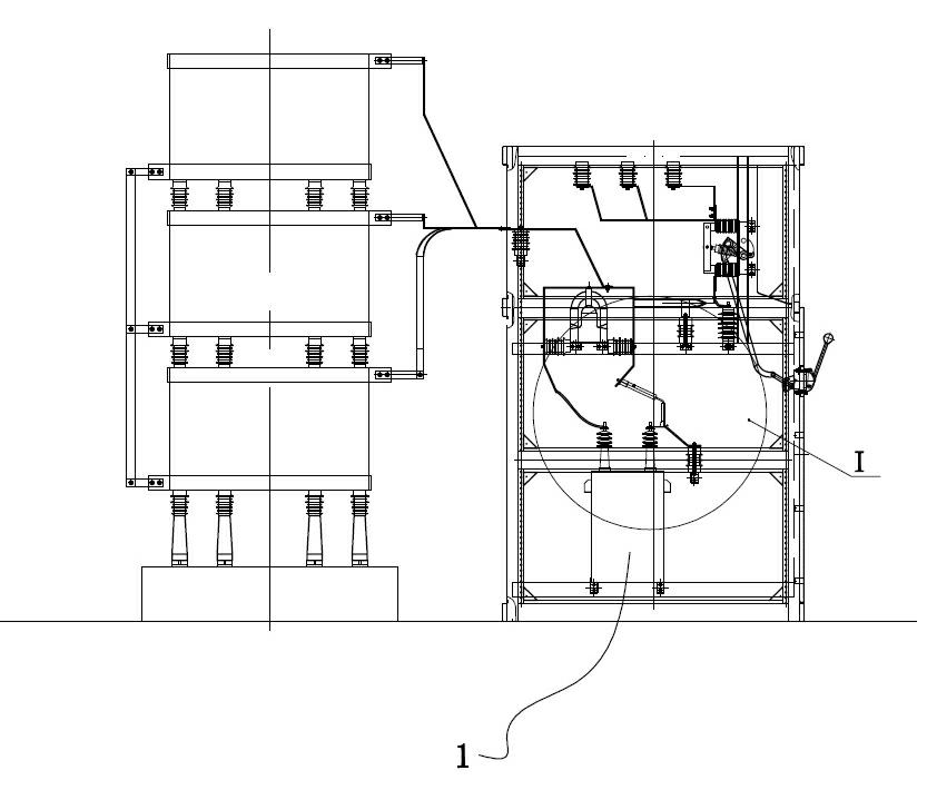
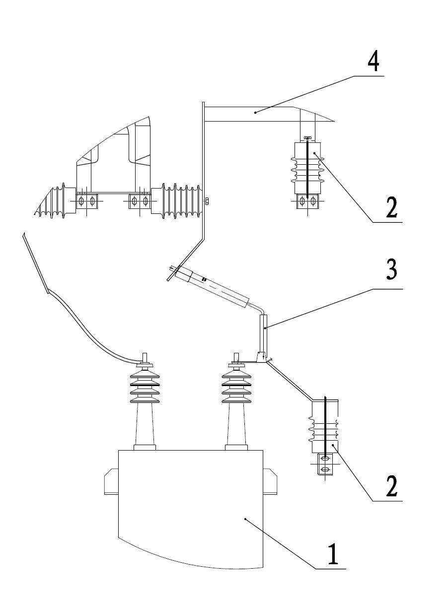
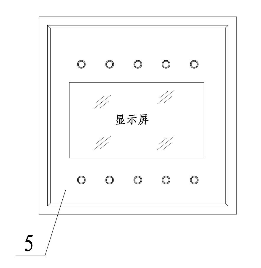
[0026] Example: A fuse state monitoring protection device (see attached figure 1 Attached figure 2 Attached image 3 ), set in the box, including a high-voltage spray fuse 3 connected to the capacitor 1 and a controller 5 connected to the fuse. A voltage sensor 2 is connected to both ends of the fuse, and the voltage sensor is connected to the controller. The capacitor is connected with an alarm, and the alarm is connected with the controller. Each connection adopts a combination of row 4 and the lead. The controller is equipped with a storage module, a comparison module, a control module connected to the circuit breaker, and a display device. The alarm includes Acoustic alarm and optical alarm, each capacitor corresponds to an acoustic alarm and a light alarm. The monitoring and protection device also includes a remote communication module, which is connected to the controller and the background equipment.

[0027] A fuse state monitoring and protection method includes the foll...


PUM


Abstract

The invention relates to a fuse state monitoring protection device and a fuse state monitoring protection method, which are used for improving the protection and trouble shooting of a capacitor group in a high voltage reactive power compensation device and solve the problems that a conventional fuse does not have a state monitoring function and that specific failing points are difficult to find after the fuse fails. The fuse state monitoring protection device comprises the fuse connected with capacitors and a controller connected with the fuse, wherein the two ends of the fuse are connected with a voltage sensor respectively; the voltage sensors are connected with the controller; and each capacitor is connected with an alarm which is connected with the controller. Voltage at the two ends of the fuse is monitored, the controller performs comparison and judgment to determine the working state of the fuse, simultaneously the abnormally working fuse is accurately positioned, corresponding capacitors are protected, failing positions are convenient to investigated, response is made timely, convenience is brought to the maintenance of maintainers, and shutdown time is shortened.

Description

Technical field [0001] The invention belongs to circuit detection and protection, in particular to a fuse state monitoring protection device and a protection method used in high-voltage reactive power compensation devices to improve the protection and troubleshooting of capacitor banks. Background technique [0002] Because there are a large number of inductive loads in the power grid, such as motors and transformers, they are all inductive loads. These inductive loads severely reduce the power factor of the power grid during operation, increase power loss, and cause voltage fluctuations, which affect the safe operation of the system. The use of capacitor compensation devices is a commonly used method to improve power factor, reduce line loss, and improve power quality. At present, the protection of capacitors mainly adopts open delta protection, current unbalance protection, differential voltage protection, differential current protection, etc. These protections are aimed at the...

Claims


Application Information

Patent Timeline
IPC IPC(8): H02H7/22H02H3/26H02H3/04H02J13/00G01R31/07G01R31/74
CPCY04S10/522Y04S10/52
Inventor 杨圣利邵萍萍李支海
Owner 杭州银湖电气设备有限公司
Learn More