
Method and apparatus for antenna mapping selection in MIMO-OFDM wireless networks

An antenna, the selected technology, applied in the direction of radio transmission system, diversity/multi-antenna system, space transmit diversity, etc., can solve the problem of not considering the utilization of smart antenna technology

Inactive Publication Date: 2011-09-14
INTERDIGITAL TECH CORP
View PDF1 Cites 39 Cited by
  • Summary
  • Abstract
  • Description
  • Claims
  • Application Information

AI Technical Summary

Problems solved by technology

[0012] The existing technology does not consider the utilization of smart antenna technology

Method used


Image

  • Method and apparatus for antenna mapping selection in MIMO-OFDM wireless networks
  • Method and apparatus for antenna mapping selection in MIMO-OFDM wireless networks
  • Method and apparatus for antenna mapping selection in MIMO-OFDM wireless networks

Examples


Embodiment

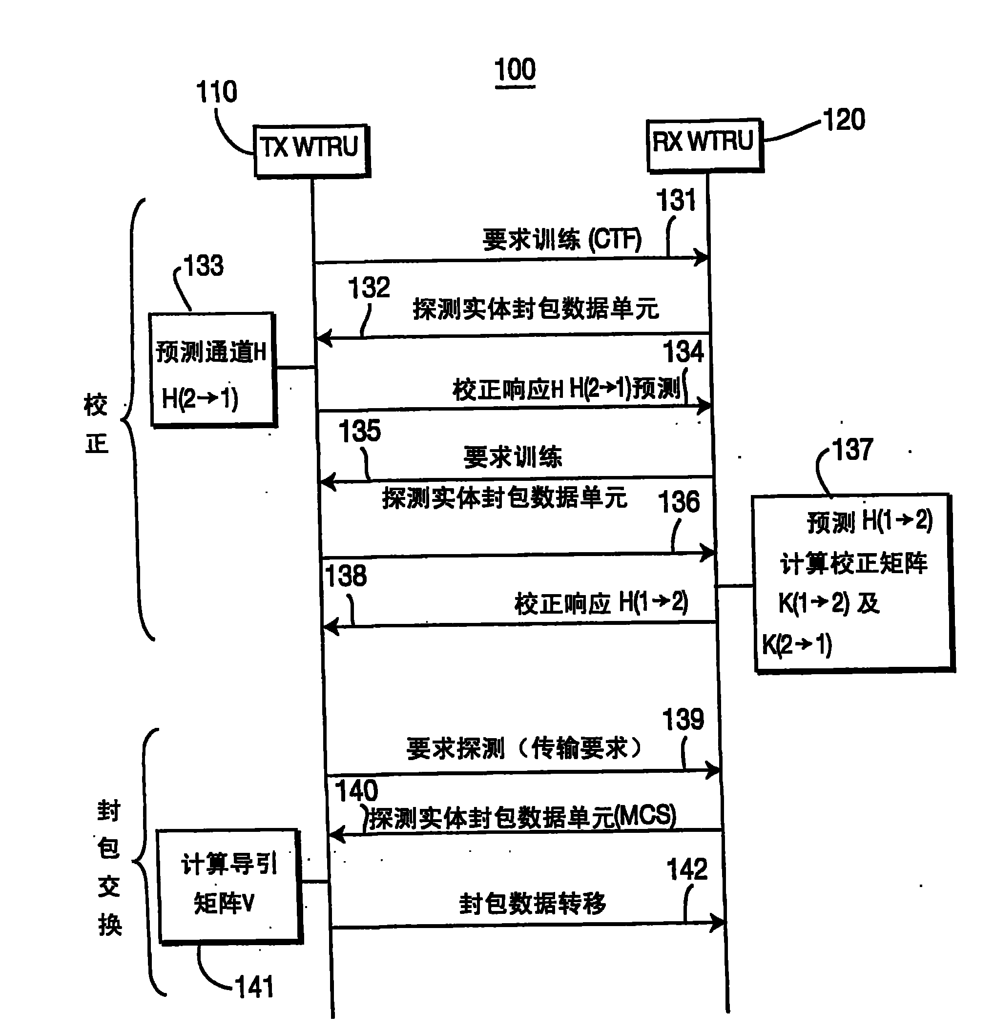
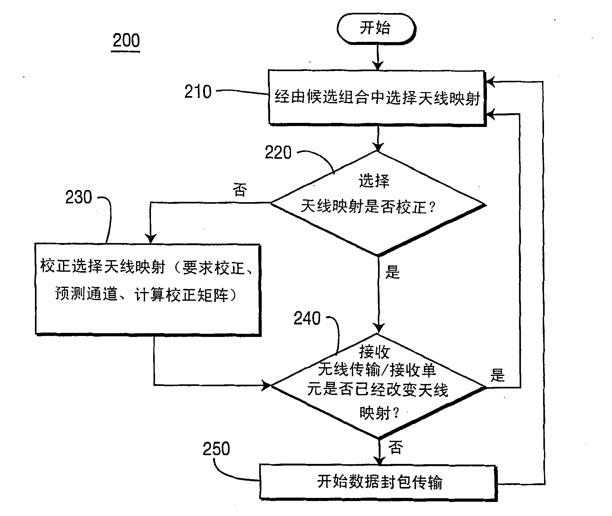
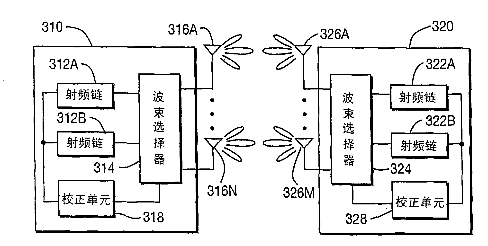
[0052] 1. A method for selecting an antenna map for communication between a transmitting WTRU (Tx WTRU) and a receiving WTRU (Rx WTRU), wherein the two WTRUs The (WTRU) is multiple-input multiple-output (MIMO) capable, and an antenna map is a combination of a single radio frequency (RF) chain and a single antenna beam, the method comprising the steps of:

[0053] selecting an antenna map from a candidate combination of currently available antenna maps at the transmitting WTRU; and

[0054] an antenna map selected at the receiving WTRU from a candidate combination of currently available antenna maps;

[0055] 2. The method as described in embodiment 1, further comprising:

[0056] determining whether to correct the currently selected antenna image;

[0057] 3. The method of embodiment 2, wherein the determination is made by the transmitting WTRU.

[0058] 4. The method of embodiment 2, wherein the determination is made by the receiving WTRU.

[0059] 5. The method as descri...


PUM


Abstract

A method and apparatus for selecting an antenna mapping in multiple-in / multiple-out (MIMO) enabled wireless communication networks. A candidate set of currently available antenna mappings is determined based upon measured long term channel conditions. An antenna mapping is selected from the candidate set, and the mapping is calibrated with a selected antenna mapping of a receiving wireless transmit / receive unit (WTRU). When the selected mappings are calibrated, packet data transmission begins. In an alternative embodiment, a calibration training frame (CTF) is used to calibrate multiple antenna mappings simultaneously or sequentially. Also disclosed are physical layer and medium access control layer frame formats for implementing antenna mapping selection according to the invention.

Description

[0001] This application is a divisional application with an application date of October 8, 2007 and an application number of 200680011280.X. technical field [0002] The present invention relates to wireless communication systems utilizing multiple-input multiple-output (MIMO) technology. In particular, the present invention relates to selecting optimal settings for multiple-input multiple-output capable multiple antenna arrays. Background technique [0003] Wireless communication devices with multiple antennas arranged in diverse architectures provide various transmission and reception benefits compared to devices with only a single antenna. Diversity is based on the fact that at any given time, the antenna with the best reception is selected for reception or transmission. While devices utilizing antenna diversity may have multiple physical antennas, signal processing has only a single set of electronic circuits, also known as a radio frequency (RF) chain. [0004] MIMO w...

Claims


Application Information

Patent Timeline
IPC IPC(8): H04B7/04H04J99/00
CPCH04B7/0413H04B7/088H04B7/0695
Inventor 车尹赫爱尔戴德·莱尔基斯·理查·鲍尔温
Owner INTERDIGITAL TECH CORP
Learn More