Fluid energy machine

An energy and fluid technology, applied in the direction of mechanical equipment, liquid fuel engines, components of pumping devices for elastic fluids, etc., can solve size and weight constraints, fluid dynamics instability, multi-stage structures that cannot be considered, etc. question

Inactive Publication Date: 2011-09-14
SIEMENS AG
View PDF7 Cites 15 Cited by
  • Summary
  • Abstract
  • Description
  • Claims
  • Application Information

AI Technical Summary

Problems solved by technology

The device described there is only suitable for operating relatively small fluid energy machines, since the impellers arranged accordingly on the free shaft ends are limited in terms of rotordynamics in terms of size and weight.
Multi-level constructs cannot be considered in the described manner
Hydrodynamic instabilities in crevice flow are not presented as a problem

Method used


Image

  • Fluid energy machine
  • Fluid energy machine

Examples


Embodiment Construction

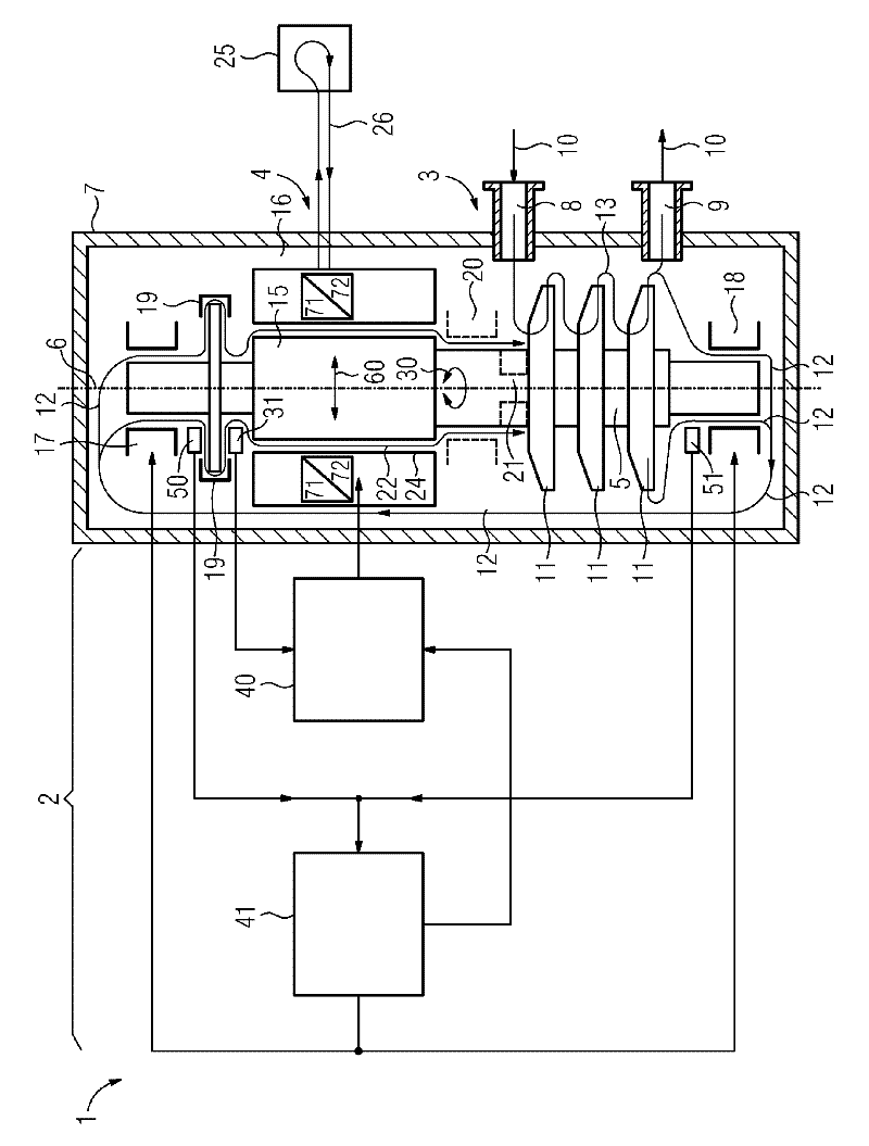
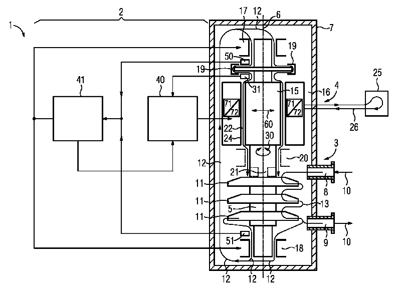
[0023] The drawing shows a longitudinal section of a fluid energy machine 1 and an adjusting device 2 as a block diagram in each case in a simplified illustration. The fluid energy machine 1 has a compressor 3 and a motor 4 which are arranged connected by means of a common shaft 5 along a longitudinal axis 6 of the shaft in a housing 7 which is gas-tight to the outside. The gas-tight housing 7 is gas-tight because no passage is provided for the shaft 5 that must be sealed by means of a shaft seal. In this regard, the fluid energy machine 1 can be described as seal-free, although there are shaft seals between the individual stages of the compressor 3 to reduce the pressure differences occurring in the stages.

[0024] The housing 7 has an inlet 8 and an outlet 9 for a process fluid 10 which is compressed by means of a compressor 3 . In addition to passing through the inlet 8 and outlet 9 or the main flow 13 of the plurality of impellers 11 of the compressor 3 , a smaller porti...


PUM


Abstract

The invention relates to a fluid energy machine (1), in particular compressor (3) or pump, having a housing (7), having a motor (4), having at least one impeller (11), having at least two radial bearings (17, 18) and having at least one shaft (5) which extends along a shaft longitudinal axis (6) and which supports the at least one impeller (11) and a rotor (15) of the motor (4), wherein the shaft (5) is mounted in the radial bearings (17, 18), wherein the motor (4) has a stator (16) which at least partially surrounds the rotor (15) in the region of the motor (4), and wherein a gap (22) which extends in the circumferential direction and along the shaft longitudinal axis (6) is formed between the rotor (15) and the stator (16) and between the rotor (15) and the radial bearings (17, 18), which gap (22) is at least partially filled with a fluid. Conventional fluid energy machines (1) have a restricted operating range as a result of destabilizing aerodynamic or hydrodynamic forces in the gap (22) between the stator (16) and the rotor (15). The invention aims to remedy this in that the motor (4) is also embodied as a bearing and is connected to a controller (2), which activates the motor (4) in such a way that forces (60) acting radially with respect to a shaft longitudinal axis (6) can be exerted in addition to torques (30) for driving the fluid energy machine (1).

Description

technical field [0001] The invention relates to a fluid energy machine, in particular a compressor or a pump, having a housing, a motor, at least one impeller, at least two radial bearings, at least one shaft extending along the longitudinal axis of the shaft, the bearing Carrying the at least one impeller and the rotor of the motor, wherein the shaft is mounted in the radial bearing, wherein the motor has a stator which at least partially surrounds the rotor in the region of the motor and in which A gap extending in the circumferential direction and along the longitudinal axis of the shaft is formed between the rotor and the stator and between the rotor and the radial bearing, which gap is at least partially filled with a fluid. Background technique [0002] Such fluid energy machines are currently the target of particularly intensive research efforts, since they offer the possibility of seal-free implementations. The motor, which is generally designed as an electric drive...

Claims


Application Information

Patent Timeline
Patent Type & Authority Applications(China)
IPC IPC(8): F04D13/06F04D29/048F04D25/06F04D29/058F04D29/58
CPCF16C32/0493F16C32/0497F16C32/0489F04D29/58F16C39/06F04D29/058F04D29/048F16C37/005F04D13/064F04D13/0633F04D13/0606F04D25/06F04D13/086F04D25/0686F16C2360/44
Inventor N.瓦格纳
Owner SIEMENS AG
Why Eureka
Try Eureka