Supercharge Your Innovation With Domain-Expert AI Agents!

Detection system for power tool

一种动力工具、检测系统的技术,应用在动力工具领域,能够解决难以区分状态缓解机制等问题

Inactive Publication Date: 2013-03-13
POWER TOOL INST
View PDF0 Cites 0 Cited by
  • Summary
  • Abstract
  • Description
  • Claims
  • Application Information

AI Technical Summary

Problems solved by technology

However, such systems have difficulty distinguishing certain materials that may cause false activation of state mitigation mechanisms

Method used


Image

  • Detection system for power tool
  • Detection system for power tool
  • Detection system for power tool

Examples


Embodiment Construction

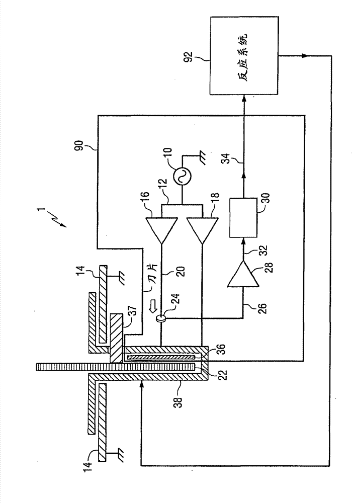
[0016] According to various embodiments, the present invention is directed to a power tool, such as a table saw, having a movable blade. The power tool includes a capacitive sensing based detector system for detecting contact between a blade and an object. The reaction system communicates with the detection system and, when triggered by the detection system, conducts a state mitigation reaction.

[0017] exist figure 1 An embodiment of a detection system based on capacitive sensing according to the present invention is shown in the idealized diagram of FIG. 1 , wherein a detection system 90 implemented in a table saw 1 is shown. It should be appreciated that the detection system 90 may be used with other types of tools and machines, such as other types of power tools, particularly tools and machines with exposed, movable (eg, rotating and / or reciprocating) blades, and These implementations are within the scope of the present invention. For example, detection system 90 may a...


PUM


Abstract

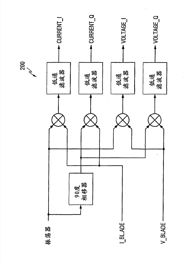
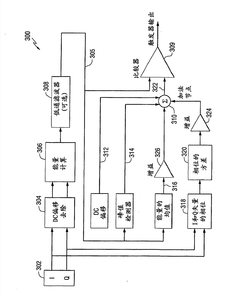
Power tool includes a movable blade and a detection system for detecting contact between the blade and an object. Detection system includes an excitation plate capacitively coupling the drive signal to the movable blade. A circuit generates an in phase component signal and a quadrature component signal from a blade current signal indicative of the instantaneous current drawn by the movable blade and calculates an energy of the blade current signal considering the in-phase and the quadrature components. The circuit compares the energy of the blade current signal to an adaptive trigger threshold to detect contact between the blade and the object based on whether the energy of the blade current signal is greater than the adaptive trigger threshold.

Description

Background technique [0001] Detection or sensing systems have been developed for various manufacturing equipment and power tools. Such a detection system is operable to trigger some type of condition mitigation mechanism by detecting or sensing an operator approaching or an operator contacting a certain part of the equipment. For example, it is known to use capacitive touch sensing systems in table saws to detect operator contact with the blade. However, such systems have difficulty distinguishing certain materials that may cause false activation of state mitigation mechanisms. Accordingly, there is a need for improved and more robust capacitive touch sensing systems. Contents of the invention [0002] In one general aspect, the present invention relates to a power tool having an improved detection system capable of distinguishing between a movable blade of the power tool and a first object believed to cause activation of a condition mitigation system or "reaction system" ...

Claims


Application Information

Patent Timeline
Patent Type & Authority Patents(China)
IPC IPC(8): G01B7/02H02H5/12B23D47/08B23Q11/00B27B5/38B27G19/02F16P3/14
CPCB23Q11/0092B27G19/02B23Q11/0082F16P3/14B23D59/001F16P3/148Y10T83/089Y10T83/8773Y10T83/7788Y10T83/773Y10T83/7726Y10T83/04Y10T83/081Y10T83/088
Inventor V·泰泰尔鲍姆D·莫斯托非R·苏普伦安特
Owner POWER TOOL INST
Features
  • R&D
  • Intellectual Property
  • Life Sciences
  • Materials
  • Tech Scout
  • Unparalleled Data Quality
  • Higher Quality Content
  • 60% Fewer Hallucinations
Learn More