FischerTropsch synthesis slurry bed reactor

A technology of Fischer-Tropsch synthesis and slurry bed, which is applied in the field of chemical engineering, can solve the problems of small scale and low efficiency of reactor space utilization, and achieve the effects of ensuring uniformity, improving space utilization, and reducing investment

Active Publication Date: 2014-03-19
CHINA PETROCHEMICAL CORP +1
View PDF7 Cites 0 Cited by
  • Summary
  • Abstract
  • Description
  • Claims
  • Application Information

AI Technical Summary

Problems solved by technology

[0004] The Fischer-Tropsch synthesis slurry bed reactor of the above-mentioned prior art is generally small in scale, and the space utilization efficiency in the reactor is low

Method used


Image

  • FischerTropsch synthesis slurry bed reactor
  • FischerTropsch synthesis slurry bed reactor
  • FischerTropsch synthesis slurry bed reactor

Examples


specific Embodiment approach

[0043] The present invention will be described in further detail below in conjunction with the accompanying drawings.

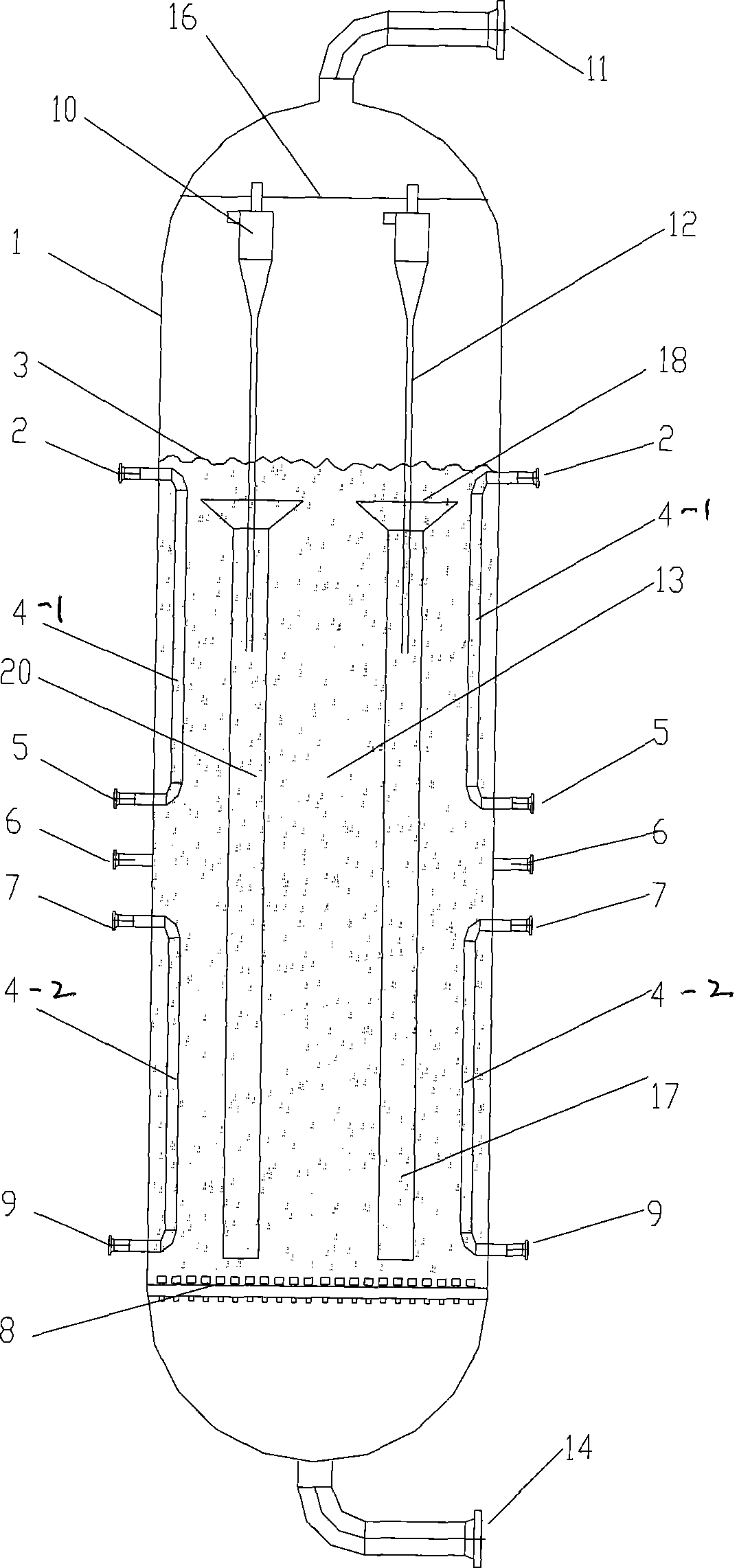
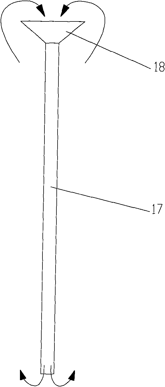
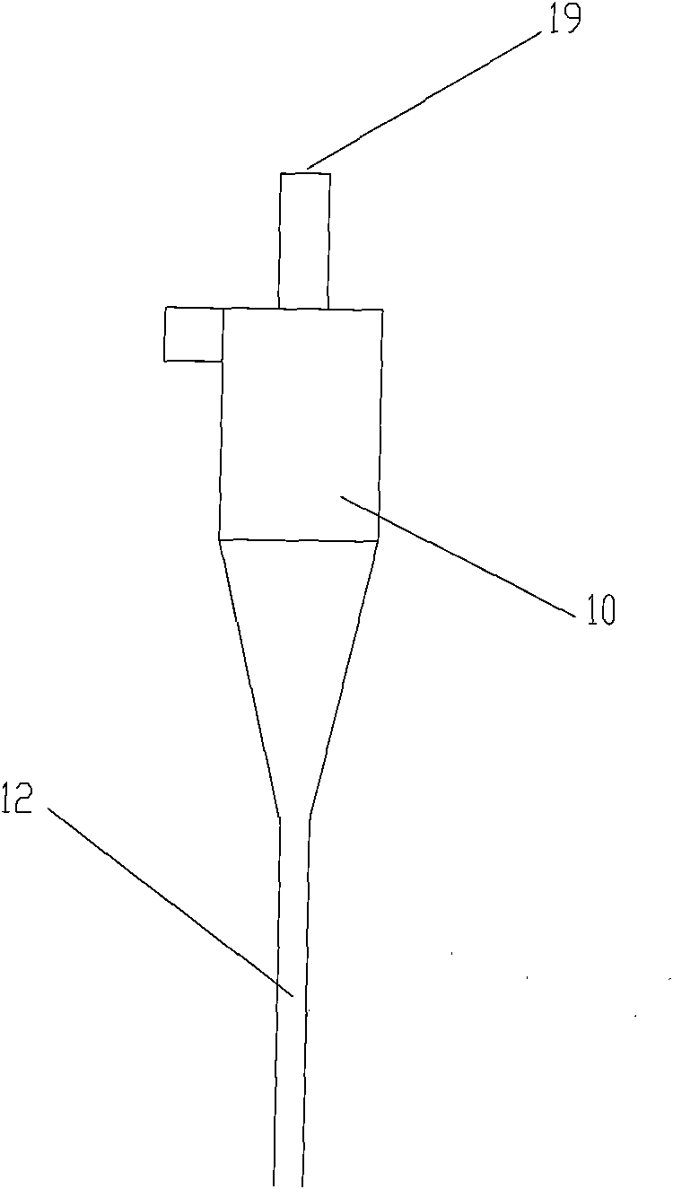
[0044] Such as figure 1 As shown, in the Fischer-Tropsch synthesis slurry bed reactor of the present invention, n circulation cups 20 are arranged in the reactor such as Figure 5 , each circulating cup 20 is submerged below the slurry bed material level 3, and the fluid inside and outside the circulating cup 20 forms a circulating flow. m gas-liquid cyclones 10 are located on the top of the reactor above the slurry bed material level 3, and the gas-liquid cyclones 10 are arranged coaxially with the circulation cups 20 in one-to-one correspondence, and the cyclone diplegs 12 extend into the corresponding circulation In the expansion mouth 18 of cup. m is less than or equal to n.

[0045] The synthesis gas enters the reactor from the synthesis gas inlet 14 at the bottom of the reactor, and is evenly distributed to the entire cross-section of the reactor th...

Embodiment

[0050] Such as figure 1 Shown, the Fischer-Tropsch synthesis slurry bed reactor shell internal diameter of the present invention is 8 meters, and the reactor tangent height is 43 meters, arranges 7 circulating cups 20 such as Figure 5 , 7 gas-liquid cyclones 10 are arranged on the top of the reactor. The normal slurry bed material level is located 32 meters above the syngas distribution plate, and the minimum material level height is 28 meters. The expansion port at the top of the circulation cup is located at a height of 27.5 meters, and the bottom of the feeding pipe of the circulation cup is located at a height of 0.3 to 0.6 meters above the syngas distribution plate.

[0051] During normal operation, the synthesis gas heated to 230-250°C is mainly composed of carbon monoxide and hydrogen, and enters the reactor from the synthesis gas inlet 14 at the bottom of the reactor at a pressure of 1.5-3.5 MPag, and is evenly distributed to the reactor through the synthesis gas di...


PUM


Abstract

The invention provides a slurry bed reactor for FischerTropsch synthesis, comprising a shell, a group of gas-liquid cyclone separators, a baffle, a coil and a synthesis gas distribution plate, wherein the shell is provided with a slurry bed layer; the reactor is provided with a group of circulation cups (20) and a group of gas-liquid cyclone separators (10); bubble cap distributors are evenly arranged on the synthesis gas distribution plate; the cyclone separator diplegs (12) of the gas-liquid cyclone separators (10) extend into an expanded port (18); and a slurry bed layer (13) is positioned above the synthesis gas distribution plate (8). The number of the gas-liquid cyclone separators (10) is not larger than that of the circulation cups (20), and each gas-liquid cyclone separator (10) and the corresponding circulation cup (20) are coaxially arranged. Fluid in and out of the circulation cups (20) circularly flows to improve the reactor airspeed and space utilization ratio; and the cyclone separator diplegs (12) extend into the expanded port (18) to accelerate the circulation of the fluid in and out of the circulation cups (20).

Description

technical field [0001] The invention belongs to the field of chemical engineering, and in particular relates to a slurry bed reactor for Fischer-Tropsch synthesis. Background technique [0002] There are three phases of gas, liquid and solid in the slurry bed reactor, and usually the solid is the catalyst, which is the core of the Fischer-Tropsch synthesis process. Gas-liquid separation and reaction heat removal are the technical difficulties of the slurry bed reactor. [0003] The existing Fischer-Tropsch synthesis slurry bed reactor takes the separation technology of liquid synthetic oil and solid catalyst as one of the research focuses. US4605678 discloses a method for separating catalyst and synthetic oil using a magnetized filter element with a high gradient magnetic field; US5811469 discloses a method for separating catalyst and synthetic oil using a downcomer filter; US6217830 discloses a method for using a hydrocarbon solvent ultra- A method for the separation of c...

Claims


Application Information

Patent Timeline
Patent Type & Authority Patents(China)
IPC IPC(8): B01J8/22C07C1/04
Inventor 刘家明郭志雄吴德飞戴文松范传宏高莉萍
Owner CHINA PETROCHEMICAL CORP
Why Eureka
Try Eureka