Dispensers and containers with dispensers

A spit, container technology, applied in a single hand-held device, closing, packaging, etc., can solve the problem of liquid extraction, prevent foreign matter from mixing, and improve the effect of preventing improper use.

Active Publication Date: 2014-10-29
FUAN KERU
View PDF5 Cites 0 Cited by
  • Summary
  • Abstract
  • Description
  • Claims
  • Application Information

AI Technical Summary

Problems solved by technology

In this conventional example, in the unused state, after removing the liquid in the container by either detaching the cap (stop ring) or pulling out the lower plunger, etc., no special consideration was given to make it impossible to return to the unused state, etc.
[0003] The retaining ring for a container with a pump disclosed in Patent Document 2 (Japanese Unexamined Patent Application Publication No. 2001-180774) is provided with a container body and is airtightly mounted on the metal mouth of the container body with a ring for sealing the container. The cover part of the pump mechanism that discharges the liquid content contained in the main body, and the container with the pump installed in the pump part on the upper end of the cover part are detachably fitted on the cover to prohibit the operation of the pump mechanism. In the state of use, the stop ring can be reinstalled by pressing down on the pump to discharge the liquid, so there is a problem that the liquid in the container may be sucked out when it is not in use.

Method used


Image

  • Dispensers and containers with dispensers
  • Dispensers and containers with dispensers
  • Dispensers and containers with dispensers

Examples


Embodiment

[0094] Figure 1 to Figure 11 An example of the present invention is shown. The specific shape of the container is not particularly limited thereto.

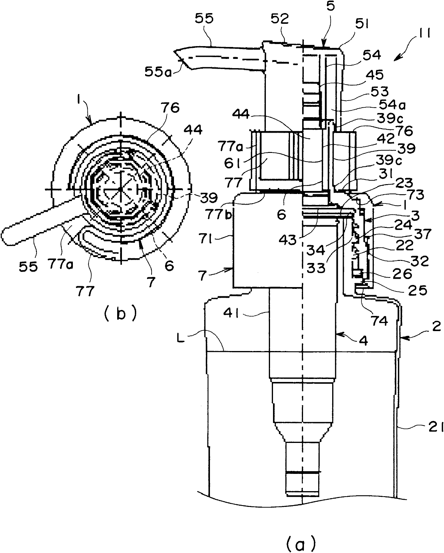
[0095] figure 1 It is a figure which shows the unused state after attaching the discharger of one Example to a container, (a) shows the side view with a part cut away, (b) shows the top view of a discharger.

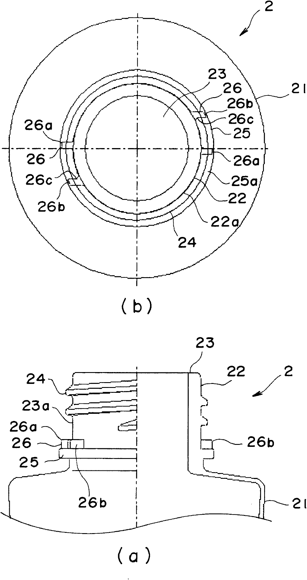
[0096] figure 2 It is a figure which shows the container of one Example, (a) shows the side view which cut away a part, (b) shows a top view.

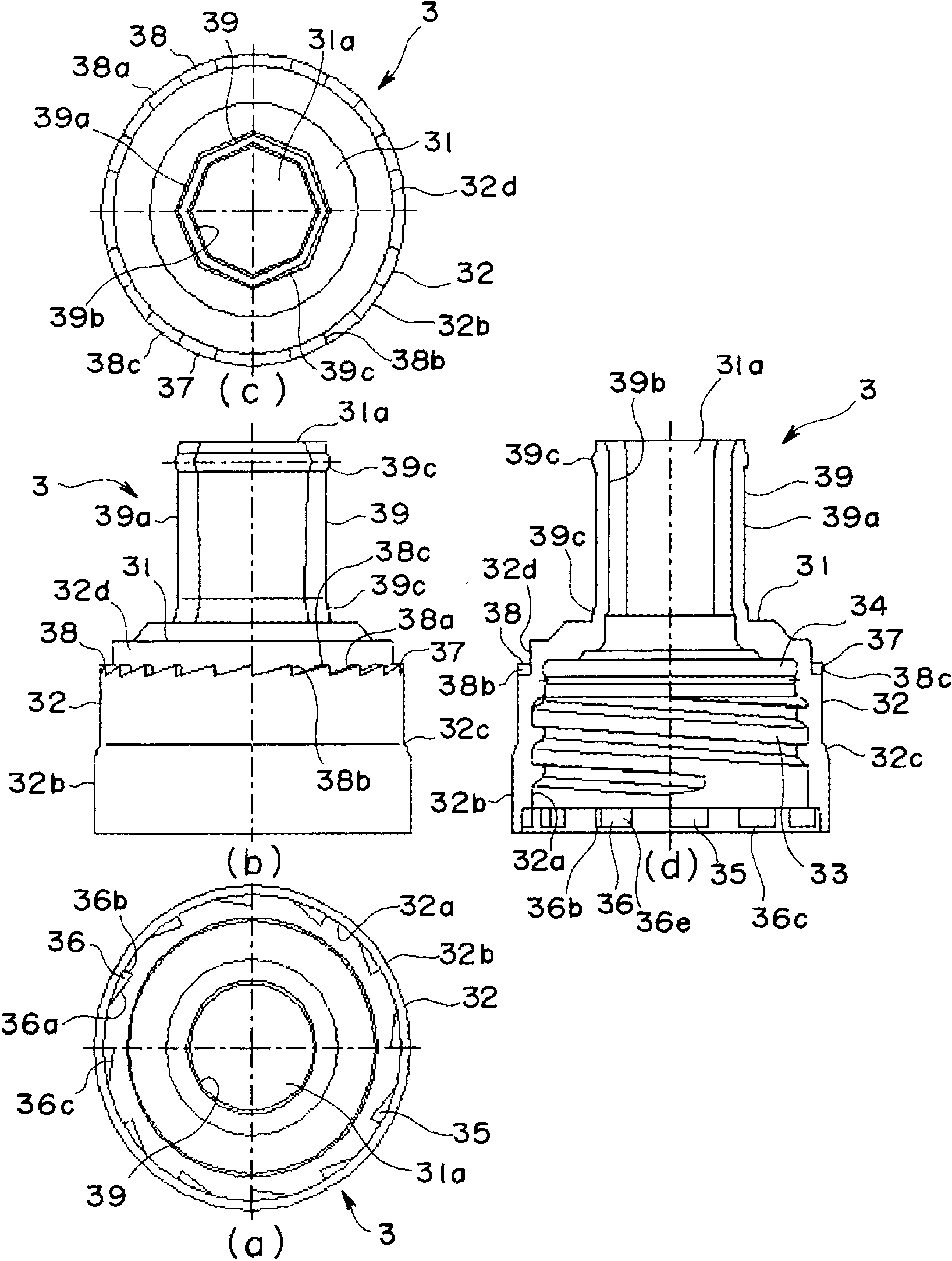
[0097] image 3 (a) is a bottom view, (b) is a side view, (c) is a top view, and (d) is a sectional view which shows the inner cover of an Example.

[0098] Figure 4 A side view of a pump showing an embodiment.

[0099] Figure 5 (a) is a side view with a part cut away, and (b) is a schematic plan view which shows the pressing head of one Example.

[0100] Figure 6 A top view of a stop ring showing an embodiment.

[0101] Figure 7 (a) is a bottom view, (b) is a side...


PUM


Abstract

The invention provides a discharge device capable of strongly maintaining an unused state and a container with the same, specifically, a discharge device composed of an inner cover (A) screwed down to a neck portion 22 of the container, a pump (B) mounted on the inner cover, a pushing-down head (C) mounted at the top of the pump, a retainer ring (D) preventing the pushing-down head from being pressed downwards, and an outer cover (E) sheathing the inner cover and the retainer ring, wherein the outer cover (E) is composed of a main body portion sheathing the inner cover and a shield portion sheathing the retainer ring; a ratchet mechanism is arranged between the inner cover (A) and the outer cover (E) to take effect in a direction where the inner cover is screwed on the container; and the ratchet mechanism is set in such a manner that the rotation thereof in a reverse direction is in an idle state in a state where the inner cover is completely screwed on the container; the shield portion of the outer cover (E) is disconnectable so that a structure in which the retainer ring (D) is detachable after the shield portion is disconnected is formed.

Description

technical field [0001] The present invention relates to a discharger for discharging liquid contained in a container by a pump, and a container with the discharger. Background technique [0002] In Patent Document 1 (Japanese Unexamined Patent Publication No. 2009-131807 ) and others, various types of ejectors having a structure in which a liquid stored in a container is ejected from a ejection hole of a lower head by the action of a pump have been proposed. And also proposed following structure, promptly under unused state, can not press downwardly the structure that presses down, prevents from under unused state from spewing out liquid, for example has patent document 2 (No. 2001-180774 of Japanese Patent Laid-Open Bulletin), etc. In this conventional example, in the unused state, after removing the liquid in the container by either detaching the cap (stop ring) or pulling out the lower plunger, etc., no special consideration was given to make it impossible to return to t...

Claims


Application Information

Patent Timeline
Patent Type & Authority Patents(China)
IPC IPC(8): B65D47/34B65D51/18B65D83/00
CPCB05B11/1047B05B11/1059B05B11/1002
Inventor 铃木康之
Owner FUAN KERU
Why Eureka
Try Eureka