Carbon dioxide beverage and beer pop can filling valve

A technology for cans and filling valves, which is applied in packaging, bottle filling, liquid bottling, etc. It can solve the problems of low single valve capacity, large liquid level deviation, high oxygenation of beverages or beer, and achieve high liquid level control accuracy , Eliminate liquid level fluctuations and high filling capacity

Active Publication Date: 2011-09-21
NANJING LEHUI LIGHT IND EQUIP
View PDF9 Cites 18 Cited by
  • Summary
  • Abstract
  • Description
  • Claims
  • Application Information

AI Technical Summary

Benefits of technology

This technology helps reduce the amount of air entering into containers filled with liquids while maintaining their stability for better quality productivity. By pumping down excess gases from outside through an enclosed system where they are filtered out prior to being charged onto another type of fluid or substance called filler. These techniques help prevent damage to sensitive components like electronic devices such as semiconductors used within these products.

Problems solved by technology

This patented technical problem addressed by this patents relates to improving mechanically-filled household fluid dispensing systems' performance while maintaining their production capabilities at reasonable prices without sacrificially increasing manufacturability concerns such as requiring higher levels of precision and assembly time required due to lower valve capacities and poor design that can lead to issues with leakage from imperfections like leaks caused by debris inside pipes.

Method used


Image

  • Carbon dioxide beverage and beer pop can filling valve
  • Carbon dioxide beverage and beer pop can filling valve
  • Carbon dioxide beverage and beer pop can filling valve

Examples


Embodiment Construction

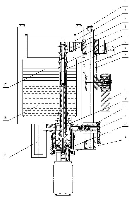
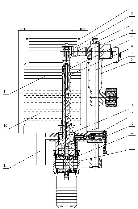
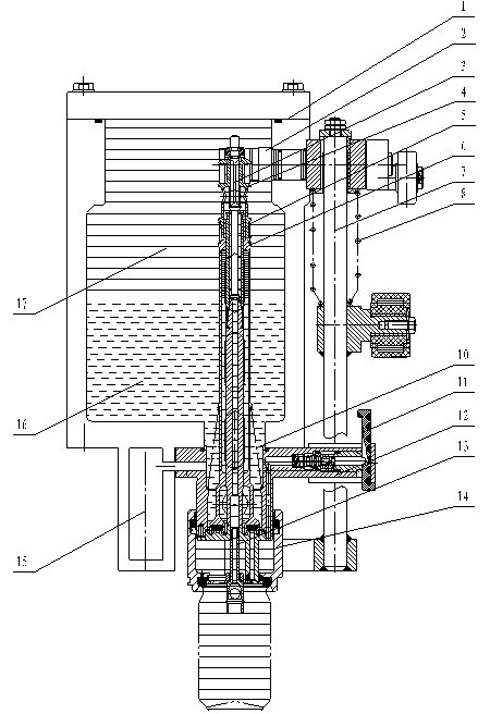
[0018] The filling valve of the present invention is installed on the rotary disc (not shown) of the filling machine, and rotates together with the rotary disc, as figure 1 As shown, the filling valve of the present invention mainly includes an annular material cylinder 1, a valve body 12 is provided at the bottom of the annular material cylinder 1, and a valve seat is installed at the bottom of the valve body 12. The lower space of the annular material cylinder 1 is used to house materials 16 , and the space above the materials is filled with back pressure gas 17 . The side wall of the annular material cylinder 1 is provided with a shift fork 2 that penetrates the material cylinder. One end of the shift fork 2 protruding from the material cylinder is connected to the eccentric wheel. The end of the shift fork 2 extending into the material cylinder is stuck on the sliding sleeve 4, and the sliding sleeve 4 is vertical In the annular material cylinder, there is a central tube c...


PUM


Abstract

The invention discloses a carbon dioxide beverage and beer pop can filling valve, which comprises an annular material tank. Backpressure gas is filled above materials in the annular material tank; the bottom of the annular material tank is provided with a valve body; a valve seat is arranged at the bottom of the valve body; a valve rod is arranged in the annular material tank; a fit surface is formed between the bottom end of the valve rod and the valve seat; a spring is arranged between the outer wall of the valve rod and the inner wall of the valve body; a filling seal cover is arranged on the outer wall of the valve body and can slide along the outer wall; and a backpressure channel for inputting the backpressure gas into pop cans to be filled and a control mechanism thereof, and a pressure relief channel for blowing down the gas in the pop cans to be filled and a control mechanism thereof are arranged in the annular material tank and the valve body. By arranging the backpressure gas and the backpressure channel, the backpressure gas blows the interiors of the pop cans before filling, and oxygen increase is reduced; and backpressure is applied, so that the pressure inside the pop cans is absolutely equal to the pressure of the backpressure gas during filling, liquid level fluctuation caused by stable state differential pressure is eliminated, and complete equipressure filling and stable filling are realized.

Description


Claims


Application Information

Patent Timeline
Owner NANJING LEHUI LIGHT IND EQUIP
Why Eureka
Try Eureka