
Improved intermittent type pressure pulp screening machine

A technology of pulp sifter and pressure sieve, which is applied in textiles, papermaking, fiber raw material processing, etc., can solve problems such as downtime, and achieve the effects of reducing power consumption and improving quality and efficiency

Inactive Publication Date: 2011-09-21
山东惠祥专利造纸机械有限公司
View PDF8 Cites 7 Cited by
  • Summary
  • Abstract
  • Description
  • Claims
  • Application Information

AI Technical Summary

Problems solved by technology

[0007] The technical problem to be solved by the present invention is the problem that the prior art pressure screener must be shut down when removing the light slag in the form of non-good pulp, and then provide a machine that can remove the light slag in the form of dry slag without stopping the work. Pressure screen machine

Method used


Image

  • Improved intermittent type pressure pulp screening machine
  • Improved intermittent type pressure pulp screening machine
  • Improved intermittent type pressure pulp screening machine

Examples


Embodiment 1

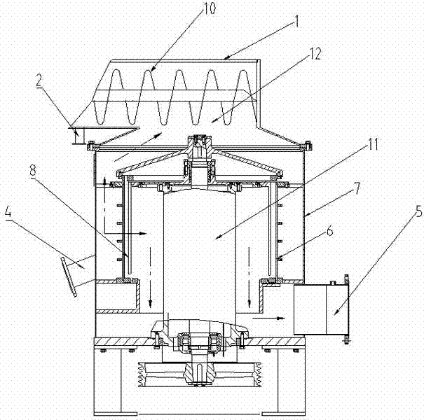
[0036] The pressure screen machine described in this embodiment is as figure 1 As shown, the pressure screen machine includes: a housing 7;

[0037] A sieve drum 6 is arranged inside the housing 7, and a rotating rotor shaft driven by a power drive device is arranged inside the cavity of the sieve drum 6, and a rotor rotor 11 is arranged on the rotating rotor shaft, and the rotor rotor 11 is located in the cavity of the sieve drum 6, and the rotor rotor 11 is provided with a rotor 8 capable of relative circular motion with the sieve drum;

[0038] A slurry inlet ( figure 1 It is a cross-sectional view of the pressure screen, and the pulp inlet is not shown in the figure because it is not on the cross-section);

[0039] A side of the sieve drum 6 is communicated with a fine pulp outlet 5;

[0040]In the housing, along the conveying direction of the light slag, a spiral slag discharger is connected to the housing near the slag discharge end 12 of the screen drum 9; the slag i...

Embodiment 2

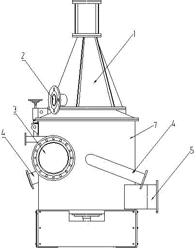
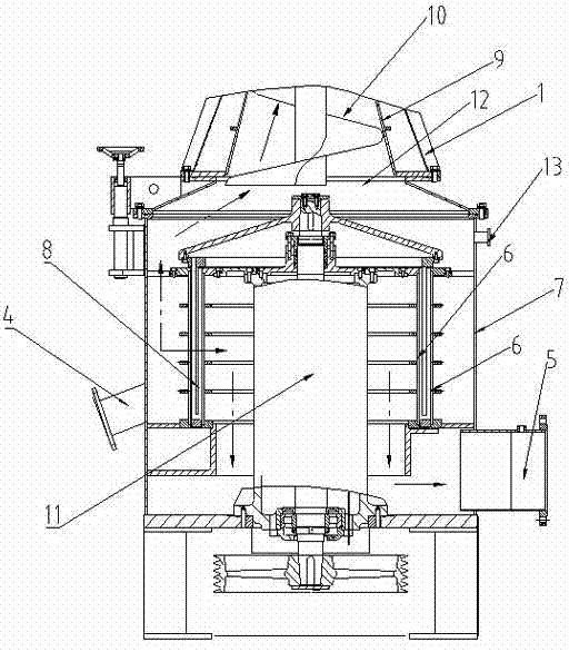
[0046] The pressure screen machine described in this embodiment is as figure 2 and image 3 As shown, the pressure screen machine includes: a housing 7;

[0047] A sieve drum 6 is arranged inside the housing 7, and a rotating rotor shaft driven by a power drive device is arranged on the central axis of the sieve drum 6, and a rotor rotor 11 is arranged on the rotating rotor shaft. The rotor 11 is provided with a rotor 8 capable of relative circular motion with the screen drum;

[0048] The sieve drum 6 in this embodiment is divided into two layers, and the two-layer pressure sieve drum 6 is respectively located on the inner side and the outer side of the rotor 8; as an optional embodiment, the two-layer pressure sieve can also be It is arranged on the same side of the rotor 8.

[0049] A slurry inlet 3 is provided on the shell 7 relative to the screen drum 6;

[0050] A side of the sieve drum 6 is communicated with a fine pulp outlet 5;

[0051] In the housing, along the...


PUM


Abstract

The invention provides a pressure pulp screening machine which comprises a shell, wherein a screen drum and a rotary wing are arranged in the shell, the rotary wing is matched with the screen drum, the rotary wing and the screen drum move relative to each other in a circumferential manner, and a pulp inlet and a good pulp outlet are arranged on the shell; and the pressure pulp screening machine is characterized in that: a spiral dreg discharging machine is arranged on the shell close to a dreg discharging end of the screen drum along the conveying direction of light dregs in a connecting way;a dreg inlet of the spiral dreg discharging machine is connected with the shell nearby the dreg discharging end; and a dreg outlet of the spiral dreg discharging machine is communicated with the outside. When the pressure pulp screening machine in the invention is adopted, the light dregs can be removed in the form of dry dregs without stopping the pressure pulp screening machine.

Description

technical field [0001] The invention relates to the field of papermaking machinery, in particular to a modified intermittent pressure screener. Background technique [0002] Pulp pressure screen, that is, the pressure screen machine is a device for screening waste paper pulp. From its structure, the pulp pressure screen is composed of a cylindrical screen drum and a rotor located in the inner cavity of the screen drum. When the rotor When rotating, the rotor on the rotor generates a hydraulic pulse near the sieve plate, so that the good pulp containing a large amount of fibers passes through the sieve plate to obtain good pulp products suitable for papermaking, and at the same time rely on the instantaneous suction pulse generated when the rotor rotates to clean the screen drum. Purification, the separation and removal of impurities in waste paper pulp. Wherein, the above-mentioned impurities in the waste paper pulp can be divided into heavy residue and light residue accord...

Claims


Application Information

Patent Timeline
IPC IPC(8): D21D5/06
Inventor 李昊
Owner 山东惠祥专利造纸机械有限公司
Learn More