

Orthogonal guide rectifier
A rectifier and deflector ring technology, which is applied in the direction of machines/engines, pumping devices for elastic fluids, non-variable pumps, etc., can solve flow wakes, resonance, installation and disassembly maintenance are not very convenient and other problems to achieve the effect of reducing the pressure gradient
Inactive Publication Date: 2011-09-21
宋波
View PDF5 Cites 6 Cited by
- Summary
- Abstract
- Description
- Claims
- Application Information
AI Technical Summary
Problems solved by technology
1. It is installed at the tail of the casing through the inlet bolt, so it is not very convenient to install, disassemble and maintain;
2. Due to the space limitation of the bolt position, the trailing edge of the counter-rotating blade is recessed at right angles, as shown in the figure above, which makes the gas flow out of the upper counter-rotating blade uneven, and this unevenness is brought into the rear flow channel and The next stage impeller, causing aerodynamic loss;
3. A number of bolts and installation accessories around are fixed at the inlet area of the guide ring, which is a blunt body from an aerodynamic point of view, which has a blocking effect on the gas, and a flow wake will be formed downstream, which will also cause aerodynamic loss;
4. The fastening bolts are installed in the inlet area of the guide ring, and each guide ring becomes a cantilever beam under the action of aerodynamic force, which is not a good design from the perspective of structural dynamics
When the frequency of the instability of the gas is close to the natural frequency of the guide ring, resonance occurs, and when the vibration is severe, the guide ring may break and cause damage to downstream components;
5. The fastening bolts are installed in the inlet area of the guide ring, and each guide ring becomes a cantilever beam under the action of aerodynamic force. When the frequency of the instability of the gas is close to the natural frequency of the guide ring, resonance occurs , increasing the vibration amplitude of the guide ring, thereby reducing the aerodynamic efficiency
Method used
View moreImage
Smart ImageViewing Examples

Examples
Embodiment Construction
Login to View More PUM
 Abstract
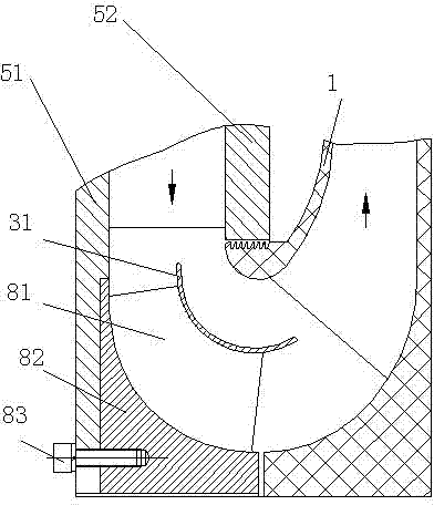
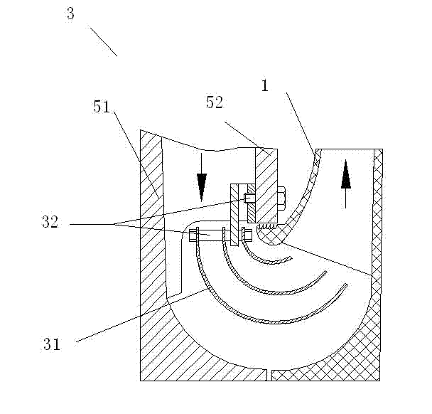
An orthogonal guide rectifier is arranged at a junction place of adjacent two-stage compression unit of a multistage centrifugal compressor and is composed of a stream guidance part for guiding for the gas and a rectification part for guiding upstream gas into a lower stage compression unit. The orthogonal guide rectifier is mainly composed of a guiding ring, radial rib pieces and a mounting seat. A plurality of radial rib pieces are uniformly distributed at the periphery of the mounting seat and fixed on the mounting seat for supporting guiding ring arranged on the top. The guiding ring is a stream guiding part for guiding, the radial rib sheets are the rectification part for rectifying. The orthogonal guide rectifier is mounted on a left wall of a shell. The orthogonal guide rectifier intakes the advantages of the traditional guiding ring, meanwhile overcomes the shortcoming of the traditional guiding ring, and abandons the mounting mode of an import bolt. And the orthogonal guide rectifier disclosed in the invention, not only has the guidance function of the traditional stream guidance device, but also has the rectification function for guiding the gas still having rotation degree at the same time of guiding the gas.
Description
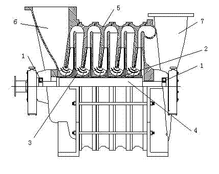
Orthogonal Steering Rectifier technical field The invention relates to an orthogonal flow guide rectifier used in a centrifugal compressor. Background technique As shown in Figure 1, the centrifugal compressor is composed of a rotor, a stator and a bearing 1 and so on. Parts such as the impeller 2 are set on the main shaft 4 to form a rotor, and the main shaft 4 is supported on the bearing 1 and driven by the power machine to rotate at high speed. The stator includes casing 5, air inlet chamber 6 and air outlet chamber 7 and other parts. A centrifugal compressor with only one impeller is called a single-stage centrifugal compressor, and a centrifugal compressor with more than two impellers is called a multi-stage centrifugal compressor. The "stages" consist of channels such as impellers and diffusers behind them. When the impeller of the centrifugal compressor rotates at high speed, due to the interaction between the blade and the gas, mainly due to the centrifugal forc...
Claims
Login to View More Application Information
Patent Timeline
 Patent Type & AuthorityApplications(China)
IPC IPC(8): F04D29/44
Inventor宋波雷先华张东峰
Owner宋波