

Pipeline heating connector
A pipeline and joint body technology, which is applied in pipeline heating/cooling, pipes/pipe joints/fittings, mechanical equipment, etc., can solve the problems that cannot be fully heated, cannot ensure the smooth flow of pipelines, and cannot circulate liquids, etc., to achieve heating Good effect, solve heating problem, high thermal efficiency
- Summary
- Abstract
- Description
- Claims
- Application Information
AI Technical Summary
Problems solved by technology
Method used
Image

Examples
Embodiment Construction
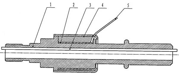
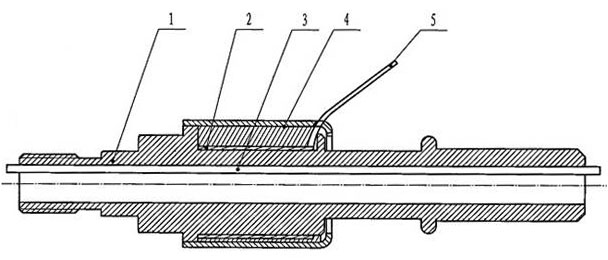
[0016] Accompanying drawing is a kind of specific embodiment of the present invention. This embodiment includes a joint body 1, a heating body 2 is arranged on the joint body 1, a protective layer 4 is arranged on the outside of the heating body 2, and a power line 5 is connected to the heating body 2; a heat conductor 3 is arranged on the inner wall of the joint body 1, and a 1 The material is 304 stainless steel, and the heating element 2 is made of PTC, electric heater or nickel-chromium alloy.
[0017] Using the pipeline heating joint of the present invention, according to different pipelines, design the pipeline heating joint of specific installation size, install it on the inlet and outlet of the tank or pump, turn on the power, and turn on the power to heat. Therefore, the beneficial effects of the present invention are: the pipeline heating joint is easy to use, can be used immediately after being connected to the power supply, has a good heating effect, can directly h...
PUM
 Abstract
Description
Claims
Application Information