Air-quality monitoring system based on electronic nose technique, and monitoring method thereof

An air quality and monitoring system technology, applied in the direction of material resistance, etc., can solve the problems of mutual interference of various gases, discrete sensors, etc.

Inactive Publication Date: 2011-09-21
CHONGQING UNIV
View PDF2 Cites 41 Cited by
  • Summary
  • Abstract
  • Description
  • Claims
  • Application Information

AI Technical Summary

Problems solved by technology

[0004] The invention provides an air quality monitoring system based on electronic nose technology and a monitoring method thereof, which can identify different response values ​​of sensors in different environments and measure

Method used


Image

  • Air-quality monitoring system based on electronic nose technique, and monitoring method thereof
  • Air-quality monitoring system based on electronic nose technique, and monitoring method thereof
  • Air-quality monitoring system based on electronic nose technique, and monitoring method thereof

Examples


Embodiment 1

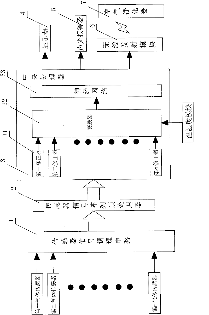
[0090] Example 1, such as figure 1 Shown: The air quality monitoring system based on the electronic nose technology of the present invention is provided with a sensor signal conditioning circuit 1. The quality detection input terminal group of the sensor signal conditioning circuit 1 is connected with a gas sensor group, and the sensor signal conditioning The output end of the circuit 1 is connected with a sensor array signal preprocessor 2, the output end of the sensor array signal preprocessor 2 is connected with a central processing unit 3, and the display end of the central processing unit 3 is connected with a display 4;

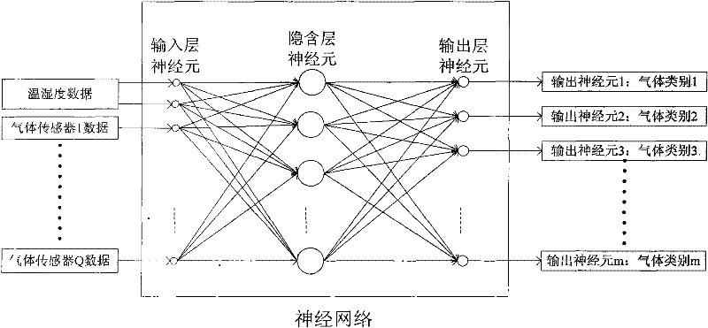
[0091] The theoretical basis of the present invention is pattern recognition, and pattern recognition requires certain preprocessing of data to obtain the best recognition effect. Assuming that the sensor array of the electronic nose system has n sensors, and the measured volatile organic compounds are measured p times, a p×n-dimensional sample set data ma...

Embodiment 2

[0118] Embodiment 2, a monitoring method of an air quality monitoring system, the key is to include the following steps:

[0119] Step 1: Use one set, that is, use the temperature and humidity module to obtain the environmental temperature and humidity digital signal g, and send it to the converter 32 in the central processing unit and the change in the sensitive resistance value of Q gas sensors to obtain Q changed gas information a, Send to sensor signal conditioning circuit 1;

[0120] Step 2: The sensor signal conditioning circuit 1 is used to convert the gas information a into Q varying voltage signals b;

[0121] Step 3: The sensor array signal preprocessor 2 converts the Q varying voltage signals b into Q digital signals b', and performs feature extraction on the Q digital signals b'to obtain Q feature extraction values ​​d;

[0122] Step 4: The Q correctors 31 respectively use the virtual resistance method to perform sensitivity compensation on a digital signal d to obtain Q d...


PUM


Abstract

The invention discloses an air-quality monitoring system based on electronic nose technique, and a monitoring method thereof. The system is characterized by being provided with a sensor signal conditioning circuit, wherein a quality detection input end group of the sensor signal conditioning circuit is connected to a gas sensor group; the output end of the sensor signal conditioning circuit is connected to a sensor array signal preprocessor; the output end of the sensor array signal preprocessor is connected to a central processing unit; and a display end of the central processing unit is connected to a display. The system has the advantages that the discreteness problem of a metallic oxide sensor and the mutual interference problem of various gases are better solved by utilizing a virtual resistance method and a specific algorithm provided by the invention, thereby greatly promoting the output precision of the system, being capable of calculating the concentration values of different outputted gases, and determining the type of the gases, and simultaneously finishing the qualitative and quantitative identification of gases, and one output of an artificial neural network represents one gas.

Description

Technical field [0001] The invention relates to an air sensor monitoring technology, specifically, an air quality monitoring system based on an electronic nose technology and a monitoring method thereof Background technique [0002] Traditional air quality electronic noses based on semiconductor metal oxide sensor arrays often only perform qualitative recognition or level recognition of odor concentration, which affects the practicality of electronic noses. Even if it has the ability of qualitative and quantitative recognition, it is realized by the way of two neural networks in series: first use one network for qualitative recognition and then use another network for quantitative recognition. This makes the electronic nose have disadvantages such as poor practicability, high algorithm complexity, poor anti-interference ability, poor accuracy, and slow operation speed. [0003] Because air quality detection electronic nose products have encountered the discreteness of metal oxide ...

Claims


Application Information

Patent Timeline
IPC IPC(8): G01N27/04
Inventor 曾孝平周宏伟田逢春黄智勇潘丽娜李红娟冯敬伟姜伟
Owner CHONGQING UNIV
Why Eureka
Try Eureka