Sensor apparatus and display apparatus

A technology of sensing equipment and components, which is applied in the field of display equipment, can solve problems such as difficult detection sensitivity, and achieve the effect of ensuring detection sensitivity and good detection sensitivity

Inactive Publication Date: 2015-07-15
SONY CORP
View PDF8 Cites 0 Cited by
  • Summary
  • Abstract
  • Description
  • Claims
  • Application Information

AI Technical Summary

Problems solved by technology

On the other hand, in the case where the capacitance value of the capacitive sensor itself is difficult to increase due to limitations of the driver circuit, detection speed, etc., although it depends on the system of the detection circuit, the sensor capacitance is limited in many cases to About several pF to tens of pF
Therefore, in the case where the change in the distance between the electrodes is extremely small (for example, about 2%), the change in capacitance between the electrodes is also extremely small, so it is extremely difficult to ensure detection sensitivity

Method used


Image

  • Sensor apparatus and display apparatus
  • Sensor apparatus and display apparatus
  • Sensor apparatus and display apparatus

Examples


no. 1 approach

[0052] [Overall structure of sensing device]

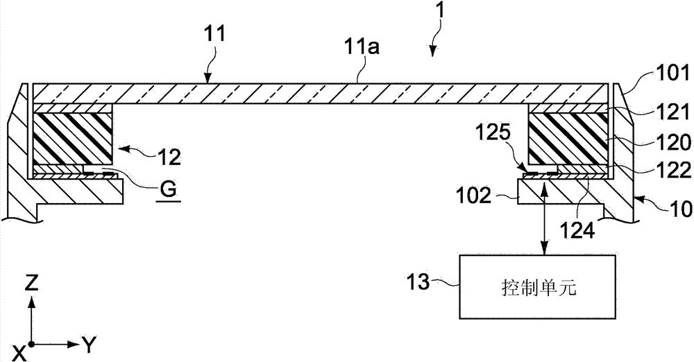
[0053] figure 1 is a schematic cross-sectional view showing a sensing device according to an embodiment of the present invention. The sensing device 1 of this embodiment is configured as a press detection sensor that detects a press input operation by a user. here, in figure 1 Among them, the Z-axis direction represents the pressing input direction relative to the sensing device 1 , and the X-axis and Y-axis directions represent two-axis directions perpendicular to the Z-axis direction and orthogonal to each other.

[0054] The sensing device 1 includes a housing 10 (first part), an input part 11 (second part), a detection mechanism 12 that detects a pressing operation on the input part 11 , and a control unit 13 that drives the detection mechanism 12 .

[0055] The input member 11 has an input operation surface 11 a for receiving a pressing operation by a user, and is mounted to the housing 10 with the input operation surface ...

no. 2 approach

[0093] Figure 7A with 7B is a sectional view schematically showing main parts of a sensing device according to a second embodiment of the present invention. It should be noted that, in the drawings, components corresponding to those in the above-described first embodiment are denoted by the same reference numerals, and detailed description thereof will be omitted.

[0094] Figure 7A The sensing device 2A shown in includes a first shield electrode 131 (third electrode portion) provided between the peripheral portion of the input member 11 and the elastic member 120 . The first guard electrode 131 is connected to the ground potential and is opposed to the electrode pair 125 facing the gap G and formed on the dielectric layer 124 in the Z-axis direction. The first guard electrode 131 is formed of a metal foil of aluminum or copper, which is connected to the peripheral portion of the input part 11 or the upper surface of the elastic part 120 .

[0095] In the sensing device ...

no. 3 approach

[0101] Figure 8A is a sectional view schematically showing a main part of a sensing device according to a third embodiment of the present invention. It should be noted that, in the drawings, components corresponding to those of the first embodiment described above are denoted by the same reference numerals and their detailed descriptions are omitted.

[0102] The sensor device 3 of this embodiment includes a detection mechanism 22 having a pair of electrodes 225 forming a plurality of capacitances between the input part 11 and the housing 10 . The electrode pair 225 includes a first electrode part 225a and a second electrode part 225b. The first electrode part 225a is disposed on the dielectric layer 124 so as to face the air layer in the gap G. As shown in FIG. The second electrode part 225b is provided between the input member 11 and the elastic member 120 . The first electrode part 225a and the second electrode part 225b are opposed to each other in the Z-axis direction...


PUM

PropertyMeasurementUnit
Thicknessaaaaaaaaaa
Thicknessaaaaaaaaaa
Thicknessaaaaaaaaaa

Abstract

A sensor apparatus includes a first member, a second member, and a detection mechanism. The second member is relatively movable in a first direction with respect to the first member. The detection mechanism includes an elastic member arranged between the first member and the second member, a support that is provided between the first member and the elastic member and forms an air layer between the first member and the elastic member, the air layer having a thickness changed by an elastic deformation of the elastic member, and an electrode pair that forms a plurality of capacitances including a capacitance component changed in accordance with a change of the thickness of the air layer. The detection mechanism outputs a detection signal on a movement amount of the second member in the first direction based on a change of a combined capacitance of the electrode pair.

Description

technical field [0001] The present invention relates to a sensing device that detects, for example, a pressing operation by a user, and to a display device including the sensing device. Background technique [0002] In recent years, portable information processing devices typified by mobile phones have become increasingly multifunctional, and a structure in which a display unit provided to a casing is used as a user interface has been proposed. For example, Japanese Patent Application Laid-Open No. 2009-134473 discloses an electronic device including a touch panel for detecting an input operation position on a display unit, and a press for detecting an input operation force as a change in resistance between electrodes. Detect sensor. Furthermore, Japanese Patent Application Laid-Open No. Hei10-198503 discloses a force detecting touch pad for detecting a pressing on a touch surface as a change in resistance between electrodes. [0003] In general, a sensor for detecting a c...

Claims


Application Information

Patent Timeline
IPC IPC(8): G06F3/044
CPCG06F3/044G06F3/041G06F3/0447G06F2203/04105
Inventor 川口裕人和田丰
Owner SONY CORP
Why Eureka
Try Eureka