Direct current (DC)-DC converter

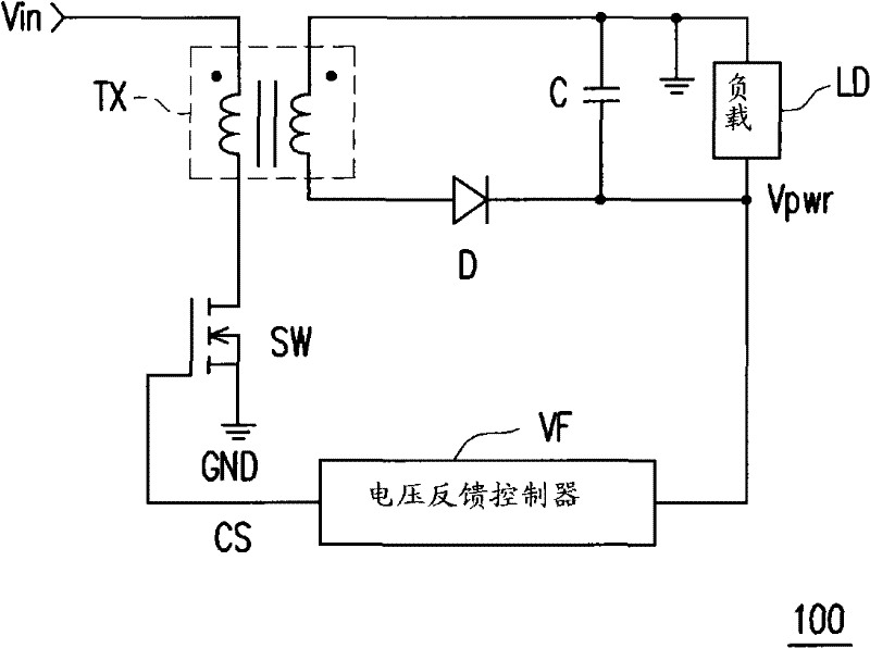
A DC-to-DC converter technology, which is used in conversion devices and instruments that convert DC power input into DC power output and output power, can solve problems such as low efficiency, large size of transformer TX, and difficulty in implementation. The effect of reducing pressure reduction efficiency, small size, and improving pressure reduction efficiency

Active Publication Date: 2011-09-21
SPI ELECTRONICS +1
View PDF3 Cites 5 Cited by
  • Summary
  • Abstract
  • Description
  • Claims
  • Application Information

AI Technical Summary

Problems solved by technology

[0004] However, since the DC-to-DC converter 100 realizes the buck-boost function at the same time mainly through the transformer TX with isolation function, the transformer TX must bear all the output power (output power), so that...

Method used


Image

  • Direct current (DC)-DC converter
  • Direct current (DC)-DC converter
  • Direct current (DC)-DC converter

Examples


Embodiment Construction

[0030] The aforementioned and other technical contents, features and effects of the present invention will be clearly presented in the following detailed description of multiple embodiments with accompanying drawings. Additionally, reference will now be made in detail to embodiments of the present invention, examples of which are illustrated in the accompanying drawings. In addition, wherever possible, elements / components using the same reference numerals in the drawings and embodiments represent the same or similar parts.

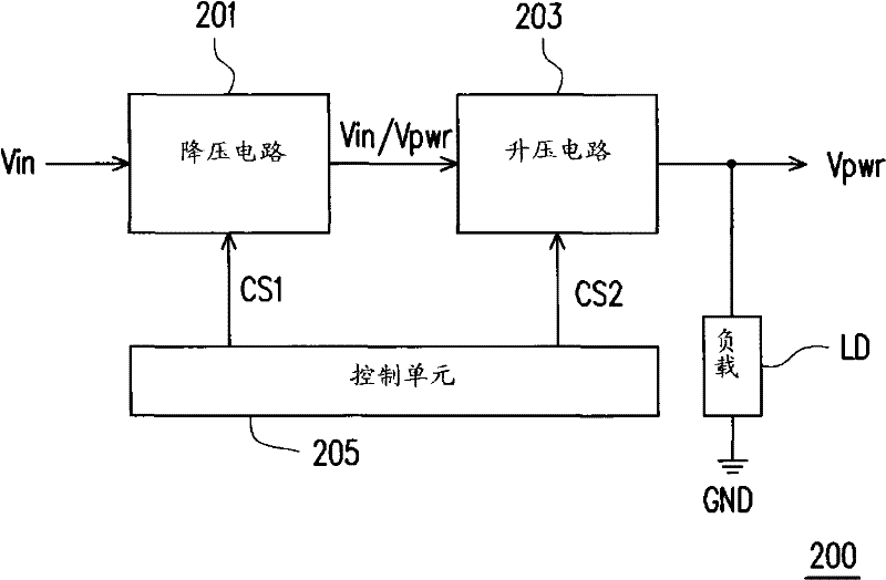
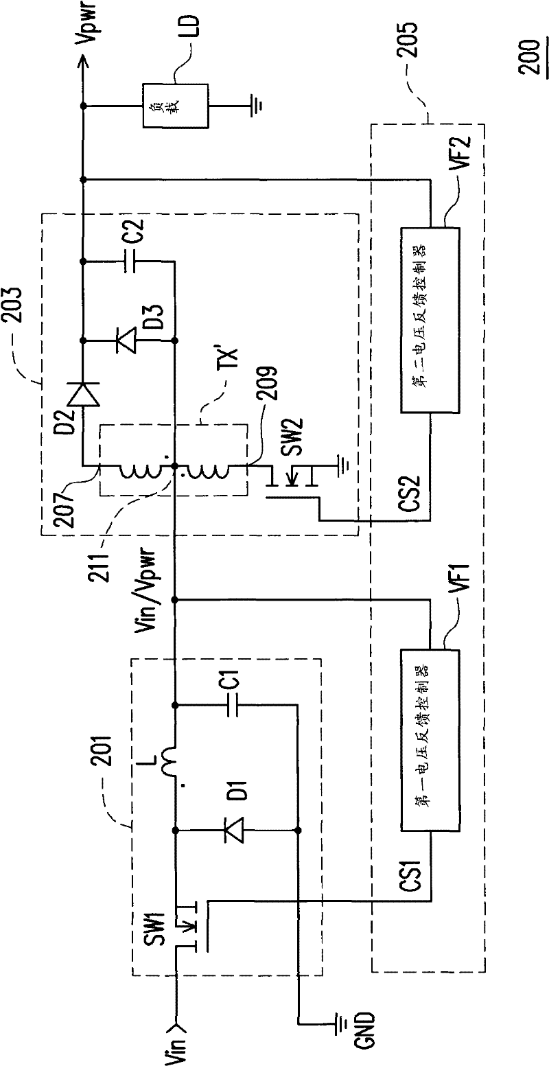
[0031] figure 2 It is a schematic block diagram of a DC-to-DC converter (DC-to-DC converter) 200 according to an embodiment of the present invention. Please refer to figure 2 , the DC-to-DC converter 200 is suitable for generating a power supply voltage (power voltage) Vpwr required by a load LD (such as an electronic device, but not limited thereto), and it includes a step-down circuit (buck circuit) 201, a step-up circuit A boost circuit 203 and a...


PUM


Abstract

The invention provides a direct current (DC)-DC converter, which is suitable for generating power supply voltage needed by a load, and comprises a step-down circuit and a booster circuit, wherein the step-down circuit is used for receiving DC input voltage and performing step-down treatment on the DC input voltage according to a first control signal so as to output the power supply voltage, or directly outputting the DC input voltage; and the booster circuit is used for receiving the power supply voltage or the DC input voltage output by the step-down circuit and performing boosting treatment on the DC input voltage which is output by the step-down circuit according to a second control signal so as to output the power supply voltage to the load, or directly outputting the power supply voltage which is output by the step-down circuit to the load.

Description

technical field [0001] The invention relates to a power supply device, and in particular to a high-efficiency DC-to-DC converter with buck-boost function. Background technique [0002] Traditionally, in order to stably / accurately provide the power supply voltage required by loads (such as electronic devices), most DC-to-DC converters are designed with a buck-boost function. figure 1 It is a schematic circuit diagram of a conventional DC-to-DC converter 100 with a buck-boost function. Please refer to figure 1 , the DC-to-DC converter 100 includes a transformer TX with an isolation function, a switch SW, a capacitor C, a diode D, and a voltage feedback controller VF. [0003] Generally speaking, the voltage feedback controller VF will continuously detect the power supply voltage Vpwr received by the load LD, and accordingly generate a control signal CS with a variable duty cycle to boost the DC input voltage Vin. ) or buck (buck). In this way, the DC-to-DC converter 100 ca...

Claims


Application Information

Patent Timeline
IPC IPC(8): H02M3/335H02M3/155H02M7/217
Inventor 蔡志昌
Owner SPI ELECTRONICS
Why Eureka
Try Eureka