Motor driving device

A driving device and motor technology, which is applied in the direction of AC motor control, electrical components, control systems, etc., can solve the problems of large computing load and complex internal structure of computing devices.

Active Publication Date: 2011-09-21
PANASONIC INTELLECTUAL PROPERTY MANAGEMENT CO LTD
View PDF5 Cites 10 Cited by
  • Summary
  • Abstract
  • Description
  • Claims
  • Application Information

AI Technical Summary

Problems solved by technology

In general, such correspondence has the problem of complicating the internal structure of the computing device and increasing the computing load.

Method used


Image

  • Motor driving device
  • Motor driving device
  • Motor driving device

Examples


Embodiment Construction

[0021] Hereinafter, a motor drive device according to an embodiment of the present invention will be described with reference to the drawings.

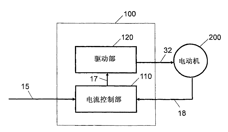
[0022] figure 1 It is a block diagram showing the motor drive device in the embodiment of the present invention. Such as figure 1 As shown, the motor drive device 100 is connected to a motor 200 and drives the motor 200 . The motor drive device 100 has a current feedback control function. In order to realize this function, the current driving the motor 200 is detected in the motor 200 , and the detected motor actual current value 18 is supplied to the motor drive 100 . In addition, in the motor drive device 100 , for example, the current command value 15 is notified from an external host computer or the like. The motor drive device 100 performs current feedback control so that the current value based on the actual current value 18 follows the current command value 15 .

[0023] The motor drive device 100 includes a current cont...


PUM


Abstract

The present invention provides a motor driving device with a current feedback control function that is controlled by a PWM. The motor driving device comprises the following components: a carrier signal generator which outputs a carrier signal of a triangular wave; a timing generator which is matched with timing of the carrier signal and outputs a current detection triggering signal and a current control triggering signal; a motor current detector which detects an average current value in a certain interval; a current controller which compares a current instruction value with an average current value and outputs a voltage instruction value; and a PWM controller which compares the carrier signal with the voltage instruction value and outputs a PWM signal, wherein, the timing generator outputs the current detection triggering signal and the current control triggering signal every N periods (N is a positive integer) of the carrier signal. The motor current detector uses an average interval of the average current value as N periods of the carrier signal.

Description

technical field [0001] The invention relates to a motor driving device with a current feedback control function. Background technique [0002] For high-speed and high-response control of servo motors, current control using a motor driver has generally been performed since the age of analog circuits. In recent years, with the progress of microcomputer and LSI technology, current control is also developing in the direction of digitalization, and it is possible to perform complex control that is difficult to achieve through analog control in terms of design and cost. High functionality has made a great contribution. [0003] Generally, current control is to detect the three-phase current of the motor, make it into a three-phase voltage command in a manner of following the current command value, and output it to an inverter composed of a plurality of semiconductor switches, and pass the DC voltage supplied by the inverter through a plurality of semiconductor switches. The comb...

Claims


Application Information

Patent Timeline
Patent Type & Authority Applications(China)
IPC IPC(8): H02P27/08
Inventor 西园胜铃木健一今田裕介
Owner PANASONIC INTELLECTUAL PROPERTY MANAGEMENT CO LTD
Why Eureka
Try Eureka