
LED lighting device

A lighting device and current technology, applied in lighting devices, electric lamp circuit layout, use of semiconductor lamps, etc., can solve the problems of uneven light, shorter LED current conduction duty ratio, etc., and achieve the effect of suppressing unevenness

Active Publication Date: 2011-09-21
PANASONIC CORP
View PDF3 Cites 8 Cited by
  • Summary
  • Abstract
  • Description
  • Claims
  • Application Information

AI Technical Summary

Problems solved by technology

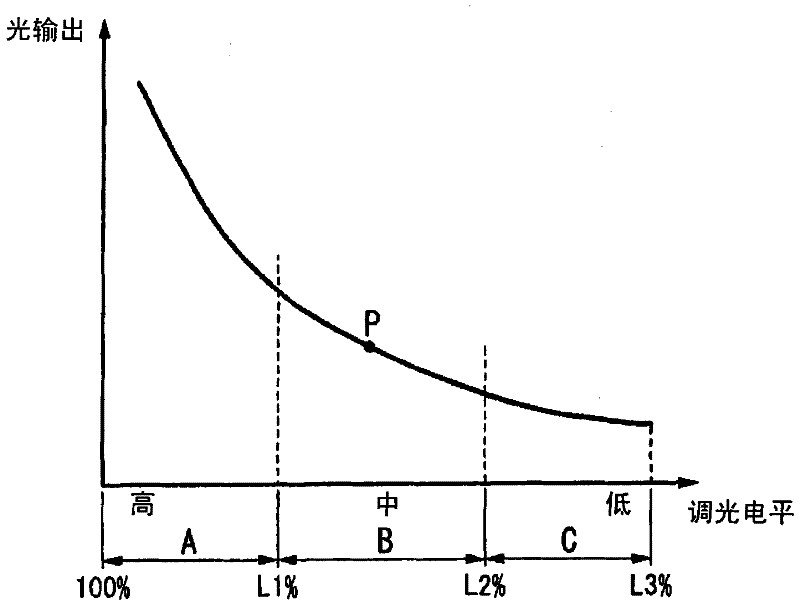
[0008] However, as the dimming level decreases and the on-duty cycle of the LED current becomes shorter, the human eye will perceive light unevenness

Method used


Image

  • LED lighting device
  • LED lighting device
  • LED lighting device

Examples


Embodiment approach

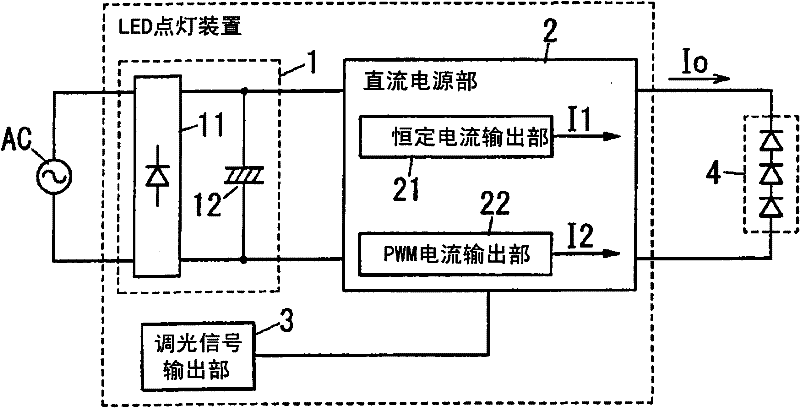
[0031] figure 1 The structure of the LED lighting device of this embodiment is shown. The LED lighting device is composed of a rectifying smoothing unit 1, a DC power supply unit 2, and a dimming signal output unit 3, and supplies an LED current Io to an LED light emitting unit 4 including one or more light emitting diodes to perform dimming control.

[0032] The rectification smoothing unit 1 includes: a rectification circuit 11 composed of a diode bridge for rectifying commercial power supply AC; and a capacitor 12 for smoothing the rectified output.

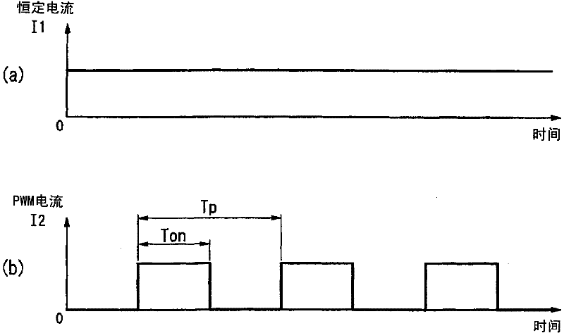
[0033] The DC power supply unit 2 includes: a constant current output unit 21 that uses the voltage across the capacitor 12 as an input power source to output a constant current I1 (first LED current) and a PWM current output unit 22 that outputs a PWM current I2 (second LED current). Then, the LED current Io which is the sum of the constant current I1 and the PWM current I2 is supplied to the LED light emitting unit 4 .

...


PUM


Abstract

The invention provides an LED lighting device capable of suppressing a flicker at an intermediate level in which a dimming level is moved between a high level and a low level. The LED lighting device includes a constant current output part 21 capable of variably adjusting an amplitude for supplying a constant current I1 with a fixed amplitude to an LED light-emitting part 4, and a PWM current output part 22 for variably adjusting an on-duty state in a PWM cycle by PWM control and supplying a PWM current with a predetermined on-duty state to the LED light-emitting part 4, wherein in an intermediate dimming range, the constant current output part 21 adjusts the amplitude of the constant current I1 in accordance with a dimming level and the PWM current output part 22 adjusts the on-duty state of the PWM current in accordance with the dimming level, so that the LED light-emitting part 4 is dimmed.

Description

technical field [0001] The invention relates to an LED lighting device capable of dimming. Background technique [0002] Conventionally, there is an LED lighting device that performs dimming control using an LED (light emitting diode) as a light source, and performs dimming by PWM control that variably controls the on-duty ratio of the LED current (for example, refer to Patent Document 1). [0003] Patent Document 1: Japanese Patent Laid-Open No. 2009-301876 [0004] Summary of the invention [0005] The problem to be solved by the invention [0006] In the case of dimming by PWM control of the LED current, an ON period in which the LED current flows and an OFF period in which the LED current does not flow are alternately repeated at a predetermined cycle. Furthermore, as the dimming becomes deeper (the dimming level decreases), the ON period in which the LED current flows becomes shorter, and the OFF period in which the LED current does not flow becomes longer (that is, ...

Claims


Application Information

Patent Timeline
Patent Type & Authority Applications(China)
IPC IPC(8): H05B37/02H05B44/00
CPCH05B33/0845H05B33/0812H05B45/395H05B45/10Y02B20/30
Inventor 水川宏光黑木芳文熊田和宏
Owner PANASONIC CORP
Learn More