
Outer rotor gear driven lubricating oil pump

A technology for external rotors and gears, which is applied to engine components, engine lubrication, and lubrication pumps. It can solve the problems of transmission stability, safety and reliability, low installation and positioning accuracy, and large space occupation. The effect of mass production, simplified connection structure and supporting parts, and reduced occupied space

Active Publication Date: 2011-09-28
HUNAN OIL PUMP
View PDF5 Cites 1 Cited by
  • Summary
  • Abstract
  • Description
  • Claims
  • Application Information

AI Technical Summary

Problems solved by technology

Its shortcomings are: due to the need to set up another transmission mechanism, it takes up a lot of space to connect with the main body of the engine, there are many transmission accessories, the installation and positioning accuracy is low, and the transmission stability, safety and reliability are difficult to guarantee.

Method used


Image

  • Outer rotor gear driven lubricating oil pump
  • Outer rotor gear driven lubricating oil pump
  • Outer rotor gear driven lubricating oil pump

Examples


Embodiment Construction

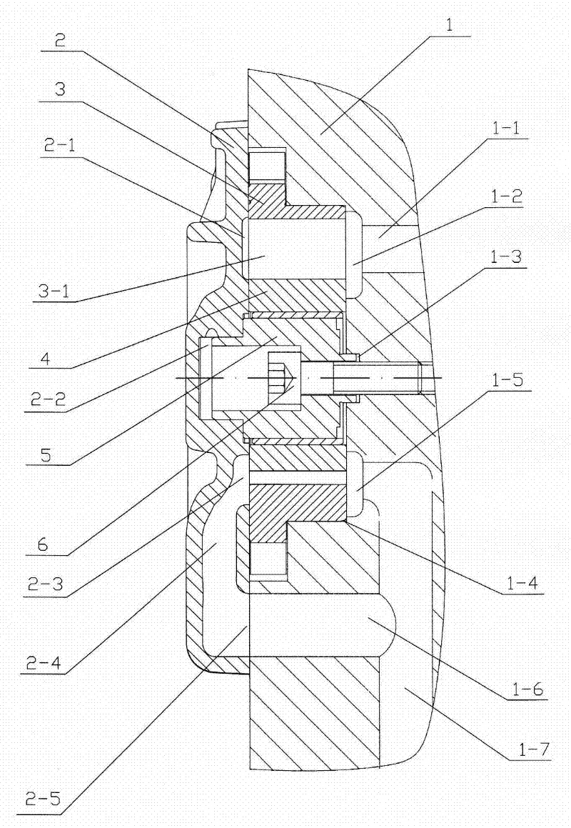
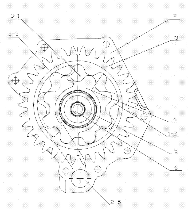
[0015] An outer rotor gear transmission oil pump comprises a body pump body 1, a pump cover 2, an outer rotor gear 3, an inner rotor 4, a boss pump shaft 5 and an inner hexagon screw 6. The bottom surface of the rotor hole 1-4 of the body pump body 1 is provided with an oil inlet passage 1-7, an oil inlet chamber 1-5, an oil outlet chamber 1-2, an oil outlet hole 1-1 and an oil passage hole 1-6 . The oil inlet chamber 1-5 and the oil passage hole 1-6 communicate with the oil inlet passage 1-7, and the oil outlet chamber 1-2 communicates with the oil outlet hole 1-1. The plane of the pump cover 2 is provided with an oil inlet chamber 2-3, a tunnel oil passage 2-4, an oil inlet 2-5 and an oil outlet chamber 2-1, wherein the oil inlet chamber 2-3 passes through the tunnel oil passage 2 -4 communicates with oil inlet 2-5.

[0016] The boss pump shaft 5 is installed on the bottom surface of the rotor hole 1-4 at the front end of the body pump body 1 with a hexagon socket head scr...


PUM


Abstract

The invention discloses an outer rotor gear driven lubricating oil pump, which comprises a body pump body, a pump cover, an outer rotor gear, an inner rotor, a boss pump shaft and an inner hexagon screw, wherein the bottom surface of a rotor hole of the body pump body is provided with an oil inlet passage, an oil inlet cavity, an oil outlet cavity, an oil outlet hole and an oil path hole; the plane of the pump cover is provided with an oil inlet cavity, a tunnel type oil passage, an oil inlet and an oil outlet cavity; the boss pump shaft is arranged on the bottom surface of the rotor hole at the front end of the body pump body by using the inner hexagon screw; a cylindrical small boss on the boss pump shaft is matched with an axle hole on the bottom surface of the rotor hole at the front end of the body pump body; the outer rotor gear is arranged in a rotor hole at the front end of the body pump body; the inner rotor is arranged on the boss pump shaft in a movable fit mode and is engaged with inner teeth of the outer rotor gear; the pump cover is arranged on a shell of the body pump body through bolts; and a cylindrical large boss on the boss pump shaft is matched with the axle hole on the pump cover. After the pump cover is arranged on the shell of the body pump body, flexibility of rotation of the inner rotor and the outer rotor gear can be guaranteed.

Description

technical field [0001] The invention relates to the technical field of oil pumps for engine lubricating systems, in particular to an oil pump driven by an outer rotor gear. Background technique [0002] The existing rotor-type oil pumps matched with the engine generally use the inner rotor to drive the outer rotor to pump oil, and the outer rotor is passively fully enclosed and installed in the oil pump casing to maintain the oil pumping efficiency of the oil pump. Its shortcomings are: due to the need to set up another transmission mechanism, it takes up a lot of space to connect with the main body of the engine, there are many transmission accessories, the installation and positioning accuracy is low, and the transmission stability, safety and reliability are difficult to guarantee. Contents of the invention [0003] The purpose of the present invention is to overcome the deficiencies in the prior art, and provide an oil pump that adopts outer rotor gear transmission, wh...

Claims


Application Information

Patent Timeline
Patent Type & Authority Applications(China)
IPC IPC(8): F01M1/02F16N13/20
Inventor 许仲秋刘光明向志奇
Owner HUNAN OIL PUMP
Learn More