Supercharge Your Innovation With Domain-Expert AI Agents!

Phase detection device and method

A phase detection and phase relationship technology, which is applied in the measurement device, the phase angle between voltage and current, and the measurement of electrical variables. The effect of strong, accurate and reliable detection, and cost reduction

Inactive Publication Date: 2011-09-28
SHENZHEN H&T INTELLIGENT CONTROL
View PDF7 Cites 0 Cited by
  • Summary
  • Abstract
  • Description
  • Claims
  • Application Information

AI Technical Summary

Problems solved by technology

A common detection method is to use a phase-locked loop integrated circuit or a high-performance microprocessor to detect. The phase-locked loop integrated circuit compares the frequency-divided output signal with the phase reference signal extracted from the signal, and uses the phase difference Change to judge the phase relationship between the load voltage and the load circuit, so as to achieve the purpose of frequency locking. The disadvantage is that the circuit is complex, and it is easy to be interfered, so that the phase cannot be locked. The use of high-performance microprocessors also has high requirements for software reliability and high cost. high disadvantage

Method used


Image

  • Phase detection device and method
  • Phase detection device and method
  • Phase detection device and method

Examples


Embodiment Construction

[0046] It should be understood that the specific embodiments described below are only to illustrate the present invention, but not to limit it.

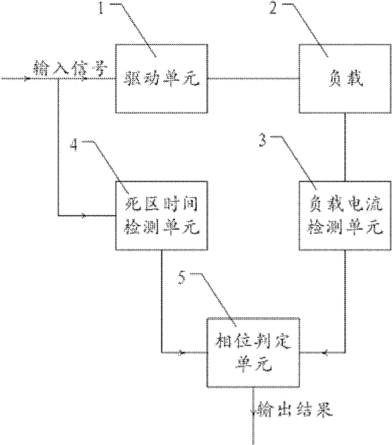
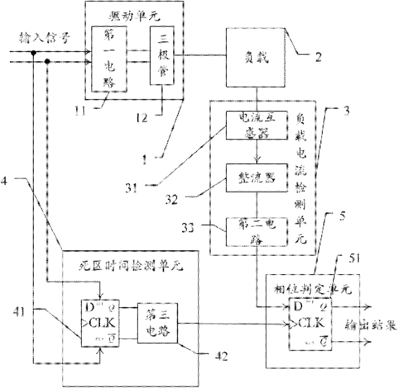
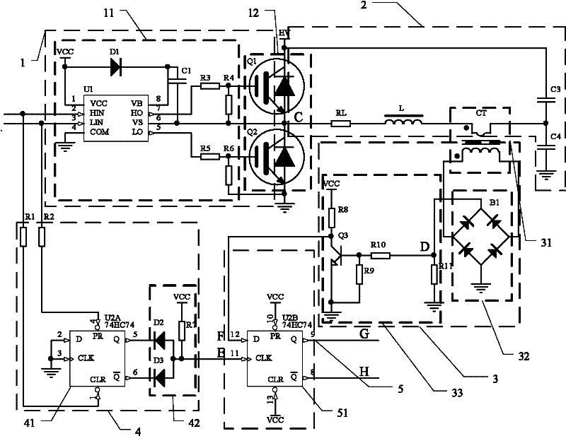
[0047] figure 1 It is a functional block diagram of an embodiment of the phase detection device of the present invention. The phase detection device is composed of a drive unit 1, a load current detection unit 3, a dead time detection unit 4 and a phase determination unit 5. When the driving unit 1 receives the input signal, the driving unit 1 outputs the driving signal to drive the load 2. The load 2 refers to the power-consuming element in the main circuit. For example, when the main circuit is an electromagnetic heating circuit, the load 2 is an electromagnetic coil and / Or other components in the LC resonant circuit composed of it, the present invention sets the dead time in the input signal, and then uses a dead time detection unit 4 to detect the dead time and a load current detection unit 3 to detect the current of the load 2. A...


PUM


Abstract

The invention relates to a phase detection device and method, which are characterized in that the dead time of a drive circuit is detected by using a dead time detection unit, the phase information of a loaded current zero-crossing point is detected by using a loaded current detection unit, and the phase relationship between the loaded voltage and the loaded current is judged according to the detection results of the dead time detection unit and the loaded current detection unit. The phase detection device and method provided by the invention are accurate in detection, strong in anti-jamming capability, and low in cost.

Description

Technical field [0001] The present invention relates to the field of digital circuits, in particular to a phase detection device and method. Background technique [0002] In many circuits, especially electromagnetic heating circuits, reasonable control of the load voltage and current phase can achieve power regulation, reduce losses, and avoid damage to high-power components. Therefore, it is of great significance to detect the load voltage and current phase. The common detection method is to use phase-locked loop integrated circuit or through high-performance microprocessor detection. The phase-locked loop integrated circuit compares the frequency-divided output signal with the phase reference signal extracted from the signal, and uses the phase difference value. Change to determine the phase relationship between the load voltage and the load circuit, so as to achieve the purpose of frequency locking. Its disadvantage is that the circuit is complicated and easy to be interfered ...

Claims


Application Information

Patent Timeline
IPC IPC(8): G01R25/00
Inventor 苏培涛
Owner SHENZHEN H&T INTELLIGENT CONTROL
Features
  • R&D
  • Intellectual Property
  • Life Sciences
  • Materials
  • Tech Scout
  • Unparalleled Data Quality
  • Higher Quality Content
  • 60% Fewer Hallucinations
Learn More