Semi-automatic stacking method for power battery core

A power battery, semi-automatic technology, applied in the direction of non-aqueous electrolyte battery, electrolyte battery manufacturing, sustainable manufacturing/processing, etc., can solve the problems of high assembly adjustment skills, long time-consuming, high operation intensity, etc., to reduce proficiency Requirements, reduce equipment costs, reduce the effect of operating intensity

Active Publication Date: 2011-09-28
SHENZHEN GEESUN INTELLIGENT TECHNOLOGY CO LTD
View PDF4 Cites 8 Cited by
  • Summary
  • Abstract
  • Description
  • Claims
  • Application Information

AI Technical Summary

Problems solved by technology

Using the fully manual lamination method, the diaphragm has no tension, the stacked cells are in the shape of tiles, the diaphragms on both sides are not folded properly, and the operation intensity is high; the automatic lamination method is adopted, the equipment cost is high, and the assembly and adjustment skills are high. , and when replacing the cell model, it needs to be reassembled and adjusted, which takes a long time

Method used


Image

  • Semi-automatic stacking method for power battery core
  • Semi-automatic stacking method for power battery core
  • Semi-automatic stacking method for power battery core

Examples


Embodiment Construction

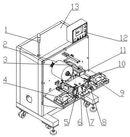
[0090] A semi-automatic lamination method for power battery cells, comprising the following steps:

[0091] 1) Pull and place the base layer diaphragm on the surface of the cell movable plate;

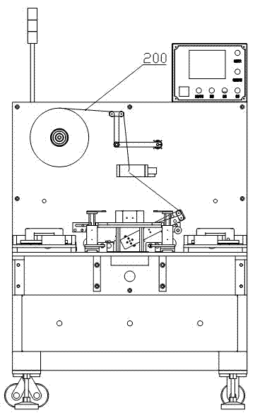
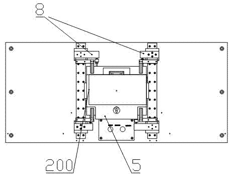
[0092] according to figure 2 Thread the diaphragm 200 as shown, and pull the diaphragm to a suitable position on the cell fixing plate 5 that exceeds the width of the pole piece. On the man-machine interface, select the manual mode, and then turn left on the button plate 6 Knob 601, the left pole clamp 8 moves to clamp the diaphragm, and its clamping state is as follows Figure 4 As shown; same as it, turn the knob 601 on the button plate 6 to the right, the right pole clip 8 moves, and the diaphragm is clamped. Such as Figure 15 shown. After doing the above actions, select the automatic mode on the man-machine interface.

[0093] 2) Lay the first cathode sheet on the surface of the base layer separator;

[0094] Press the button 904 on the left suction cup assembly 9, the suct...


PUM


Abstract

The invention relates to a semi-automatic stacking method and device for a power battery core. The semi-automatic stacking method comprises the following steps: (a) arranging a substrate-layer diaphragm; (2) stacking a first cathode plate; (3) winding a first diaphragm; (4) stacking a first anode plate; (5) winding a second diaphragm; (6) repeating the steps from the steps (2) to the step (5) to reach the preset numbers of plates and layers; (7) taking out the laminated core, wherein the step (3) and the step (5) are performed automatically and other steps are performed manually. A diaphragm winding part of the device controls a servo motor through a foot switch; a photoelectric eye photosensitive sheet is used for controlling the location of a diaphragm winding roller; left and right manual suckers can suck electrode plates in cathode plate box and a anode plate box which are arranged on the left and right sides respectively through a vacuum suction plate on the basis of vacuum generated by a vacuum valve; and then the electrode plates are stacked on the surface with wound diaphragms, thus, the plate stacking is finished; and the diaphragm winding part rotates to the same side toautomatically wind diaphragms on the surface of the electrode plates. The method can control the diaphragm under basically constant tension, thereby reducing the operation intensity, facilitating model replacement and lowering the device cost.

Description

[0001] This application is a divisional application of the patent application with the application number "200810216320.5" and the title "a semi-automatic stacking method and stacking equipment for power battery cells". technical field [0002] The invention relates to a battery lamination method and equipment, in particular to a semi-automatic lamination method and lamination equipment for power battery chips. Background technique [0003] There are two methods for the production of power battery cells: one is fully manual, which involves manually stacking the cathode and anode sheets and manually winding the diaphragm; the other is fully automatic, including automatically stacking the cathode and anode sheets , Automatic winding and unwinding of the diaphragm, automatic outer winding of the diaphragm and automatic gluing. Using the fully manual lamination method, the diaphragm has no tension, the stacked cells are in the shape of tiles, the diaphragms on both sides are not...

Claims


Application Information

Patent Timeline
Patent Type & Authority Applications(China)
IPC IPC(8): H01M10/058
CPCY02E60/12Y02E60/10Y02P70/50
Inventor 范方才陈明强
Owner SHENZHEN GEESUN INTELLIGENT TECHNOLOGY CO LTD
Why Eureka
Try Eureka