
Method and device for molding stator core with helix angle

A technology of stator iron core and helix angle, which is applied in the manufacture of stator/rotor body, etc., can solve the problem that the motor cannot be applied with precision control, and achieve the effect of ensuring repeated positioning accuracy, simple processing and convenient use.

Inactive Publication Date: 2013-10-23
FLIGHT AUTOMATIC CONTROL RES INST
View PDF0 Cites 0 Cited by
  • Summary
  • Abstract
  • Description
  • Claims
  • Application Information

AI Technical Summary

Problems solved by technology

This type of motor cannot be used in the aviation field of precision control

Method used


Image

  • Method and device for molding stator core with helix angle
  • Method and device for molding stator core with helix angle
  • Method and device for molding stator core with helix angle

Examples


Embodiment Construction

[0037] Below in conjunction with accompanying drawing and embodiment the present invention is described in further detail:

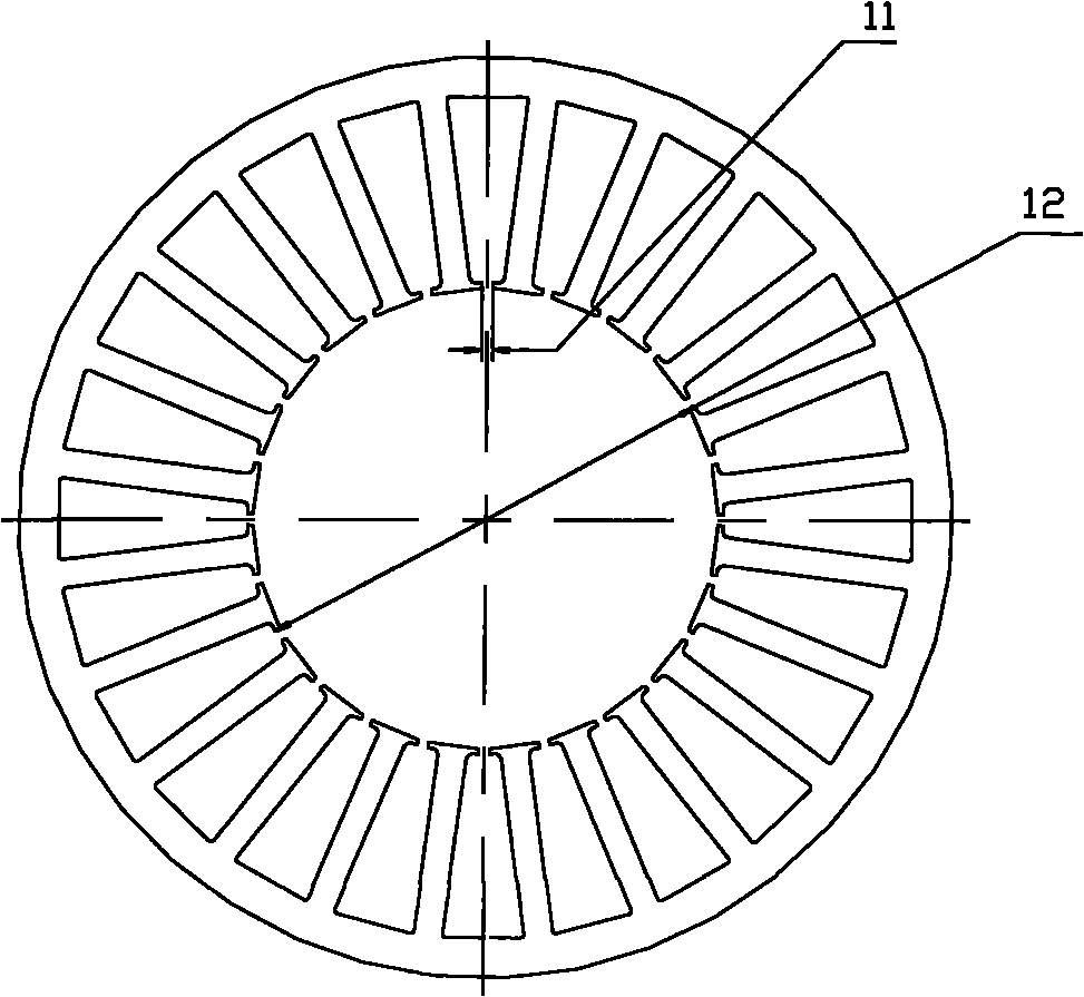
[0038] figure 1 It is the plan view of the stator punching sheet, its inner hole 12 and notch 11 are shown in the figure, the width of the notch 11 is consistent with the width of the spiral rib (51) wound on the surface of the spiral positioning pin (5) cylinder (52), in this implementation In the example, it is 1 mm.

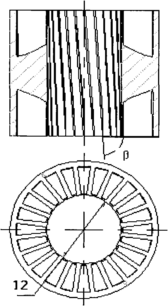
[0039] figure 2 It is a schematic diagram of a stator core with a helix angle. Several stator punches are pressed together according to certain requirements to form a stator core with a helix angle. After forming, all stator punches are concentric, and adjacent stator punches The teeth are staggered by a certain angle β around the center of rotation between the plates.

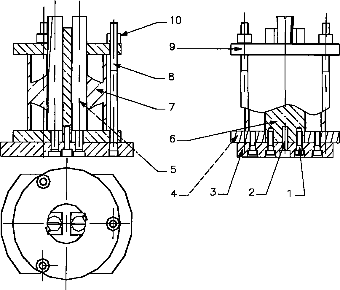
[0040] Such as image 3 , a motor stator core device with a helix angle, consisting of screws (1), cylindrical pins (2), bottom plate (3), backing plate (4), helica...


PUM


Abstract

The invention discloses a method and a device for molding a stator core with a helix angle. The device consists of bolts (1), a cylindrical pin (2), a bottom plate (3), a backing plate (4), helix positioning pins (5), a central positioning pin (6), a fastening bolt (8), a pressure plate (9) and nuts (10). Two symmetrical square grooves are axially machined on the central positioning pin (6). The two helix positioning pins (5) are arranged in the two symmetrical square grooves respectively. The outer surface part (21) of the cylindrical pin is in fit with an inner hole (12) of stator stamped steel. The surface of a cylinder (52) of the helix positioning pin (5) is wound with a slender helix bar (51) of which the helix angle is beta. In the method and the device, a split structure formed by separating central positioning from helix positioning makes the de-molding of the stator core from the device possible; in addition, the device is simple to machine and convenient to use, changes the conventional method in which a line in space replaces a curve in space in motor stator agglutination, and can fully meet the theoretical designing requirements of an obliquely slotted motor stator.

Description

technical field [0001] The invention belongs to product forming technology, in particular to a method and device for forming a motor stator core with a helix angle. Background technique [0002] The cogging torque of the motor is generated by the interaction between the magnetic field of the permanent magnet of the motor and the cogging, which will cause torque ripple and may even cause motor resonance. The inclined slot motor has been used in some special occasions because it can effectively eliminate the cogging torque, reduce the moment of inertia of the motor, reduce the electromechanical time constant, and improve the response speed of the motor to signals. However, due to the limitation of the processing method of the stator and rotor of the chute motor, the output parameters of the motor cannot meet the design requirements, which limits the application range of the chute motor. [0003] In the past, the gluing of the stator and rotor of the military chute motor used ...

Claims


Application Information

Patent Timeline
Patent Type & Authority Patents(China)
IPC IPC(8): H02K15/02
Inventor 田晔
Owner FLIGHT AUTOMATIC CONTROL RES INST
Learn More