Ultrasound diagnosis apparatus, image processing apparatus, and image processing method

A diagnostic device, ultrasonic technology, applied in the direction of acoustic wave diagnosis, infrasonic wave diagnosis, ultrasonic/sonic wave/infrasonic wave diagnosis, etc., can solve the problems of poor visual recognition of observed objects, movement of biological tissues, etc., and achieve the effect of improving visual recognition

Inactive Publication Date: 2011-10-05
KK TOSHIBA +1
View PDF7 Cites 8 Cited by
  • Summary
  • Abstract
  • Description
  • Claims
  • Application Information

AI Technical Summary

Problems solved by technology

However, generally speaking, when the ultrasonic probe is brought close to the body surface of the subject to observe the living tissue at the lower part of the body surface, the body surface of the subject may be pressed by the movement of the ultrasonic probe and become the object of observation. The movement of biological tissues
That is, in the intrinsic display method of the above-mentioned ultrasonic diagnostic apparatus, not only in the diagnosis of the malignancy of the neoplastic lesion but also in the image diagnosis using the ultrasonic image, the visibility of the observed object in the ultrasonic image may also deteriorate. The problem

Method used


Image

  • Ultrasound diagnosis apparatus, image processing apparatus, and image processing method
  • Ultrasound diagnosis apparatus, image processing apparatus, and image processing method
  • Ultrasound diagnosis apparatus, image processing apparatus, and image processing method

Examples


Embodiment Construction

[0036]Embodiments of the ultrasonic diagnostic apparatus will be described in detail below with reference to the drawings.

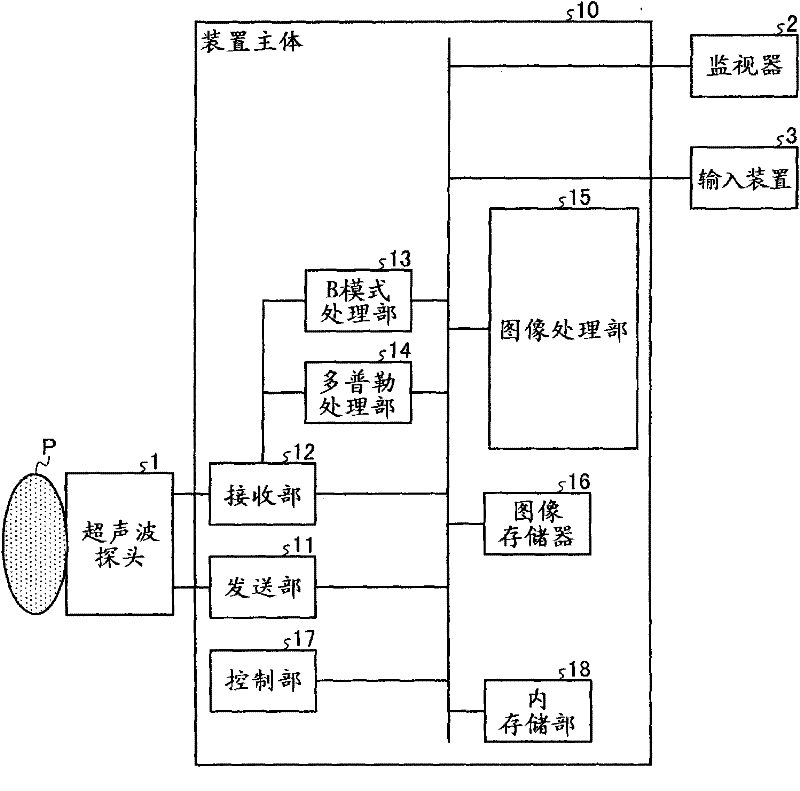
[0037] First, the configuration of the ultrasonic diagnostic apparatus related to Embodiment 1 will be described. figure 1 It is a diagram for explaining the ultrasonic diagnostic apparatus related to the first embodiment. Such as figure 1 As shown, the ultrasonic diagnostic apparatus according to the first embodiment is composed of an ultrasonic probe 1 , a monitor 2 , an input device 3 , and an apparatus main body 10 .

[0038] The ultrasonic probe 1 has a plurality of piezoelectric vibrators that generate ultrasonic waves based on drive signals supplied from a transmission unit 11 of the device main body 10 described later, and receive reflected waves from the subject P and convert them into electric signal. In addition, the ultrasonic probe 1 has a matching layer provided in the piezoelectric vibrator, a backing material for preventing ultrasoni...


PUM


Abstract

The invention relates to an ultrasound diagnosis apparatus, an image processing apparatus, and an image processing method. The ultrasound diagnosis apparatus includes an image creating unit, a motion-vector calculating unit, a corrected-image creating unit, and a control unit. The image creating unit creates a plurality of ultrasound images in time series; and the motion-vector calculating unit calculates a motion vector of a local region between two successive ultrasound images (a first image and a second image) in time series among the ultrasound images created by the image creating unit. The corrected-image creating unit then creates a corrected image corrected from the second image, based on a component of a scanning line direction of ultrasound in the motion vector calculated by the motion-vector calculating unit. The control unit then performs control so as to cause a certain monitor to display the corrected image created by the corrected-image creating unit.

Description

[0001] Cross References to Related Applications [0002] This application is based on and claims priority from prior Japanese Patent Application No. 2010-081030 filed on March 31, 2010 and prior Japanese Patent Application No. 2011-017988 filed on January 31, 2011, all of which The contents are incorporated by reference in this application. technical field [0003] The present invention relates to an ultrasonic diagnostic device, an image processing device, and an image processing method. Background technique [0004] Conventionally, ultrasonic diagnostic devices are smaller in size than other medical image diagnostic devices such as X-ray diagnostic devices, X-ray CT (Computed Tomography) devices, and MRI (Magnetic Resonance Imaging) devices. Devices that can be easily operated close to the body surface, for example, can display in real time (real time) the movement of the subject such as heart beating or fetal movement, and thus play an important role in today's medical c...

Claims


Application Information

Patent Timeline
Patent Type & Authority Applications(China)
IPC IPC(8): A61B8/00
CPCG01S7/52042G01S7/5205A61B8/485A61B8/469G01S7/52071A61B8/08
Inventor 神山直久
Owner KK TOSHIBA
Why Eureka
Try Eureka