Striking device for elevating of mode locked shaft component

A toggle device and shaft assembly technology, which is applied in the field of mechanical structures for opening and closing of a rotary die set, can solve the problems of increasing the failure rate, accelerating the wear of the clamping shaft, increasing the weight, etc., to reduce the moment of inertia and centrifugal force, smooth The effect of free lifting and prolonging the service life

Inactive Publication Date: 2011-10-05
GUANGZHOU TECH LONG PACKAGING MACHINERY CO LTD
View PDF0 Cites 8 Cited by
  • Summary
  • Abstract
  • Description
  • Claims
  • Application Information

AI Technical Summary

Problems solved by technology

However, for more than ten years, the design of the bottle blowing machine generally adopts a biaxial mold clamping mechanism, and a set of guide shaft assemblies (see figure 1 05) is a guide, and another set of clamping shaft assembly (see figure 1 01) is to drive the clamping pin on it to insert or withdraw from the lock nostril of the mold base through the lifting movement, so that the left and right mold bases can be opened and closed under the action of the opening and closing mold linkage mechanism to drive the mold to open at the same time Or closed, so that the finished bottle can be taken out from the mold cavity, and the preform can be sent into the mold cavity immediately. This biaxial lifting structure is undoubtedly feasible for medium and low speed bottle blowing machines, but in When the speed of the fully automatic rotary high-speed blow molding machine is increased to a certain limit, its inherent shortcomings are reflected. The phenomenon of interference (holding) often occurs when the two axes rise and fall at the same time, which leads to the unsmooth opening of the mold base, and then Causes downtime, increases the failure rate
And because of the addition of a set of clamping shaft guide components, the fast-running bottle blowing main machine adds another weight, which increases the moment of inertia and centrifugal force of the machine. kind of constraints
Also, when wheel 1 (i.e. figure 1 03) when running to the guide rail of the clamping shaft, due to the inertial force of the machine, the roller 1 has an impact force on the guide rail of the clamping shaft, and at the same time, the roller 1 is also affected by the reaction force from the guide rail of the clamping shaft , due to the lateral action of this reaction force on the clamping shaft, the clamping shaft is bent and deformed. This bending deformation makes the clamping shaft more likely to suffocate and cause shutdown failures, and also accelerates the wear of the clamping shaft , which greatly shortens the service life of the clamping shaft

Method used


Image

  • Striking device for elevating of mode locked shaft component
  • Striking device for elevating of mode locked shaft component
  • Striking device for elevating of mode locked shaft component

Examples


Embodiment Construction

[0016] The present invention will be further described below in conjunction with the accompanying drawings and specific examples.

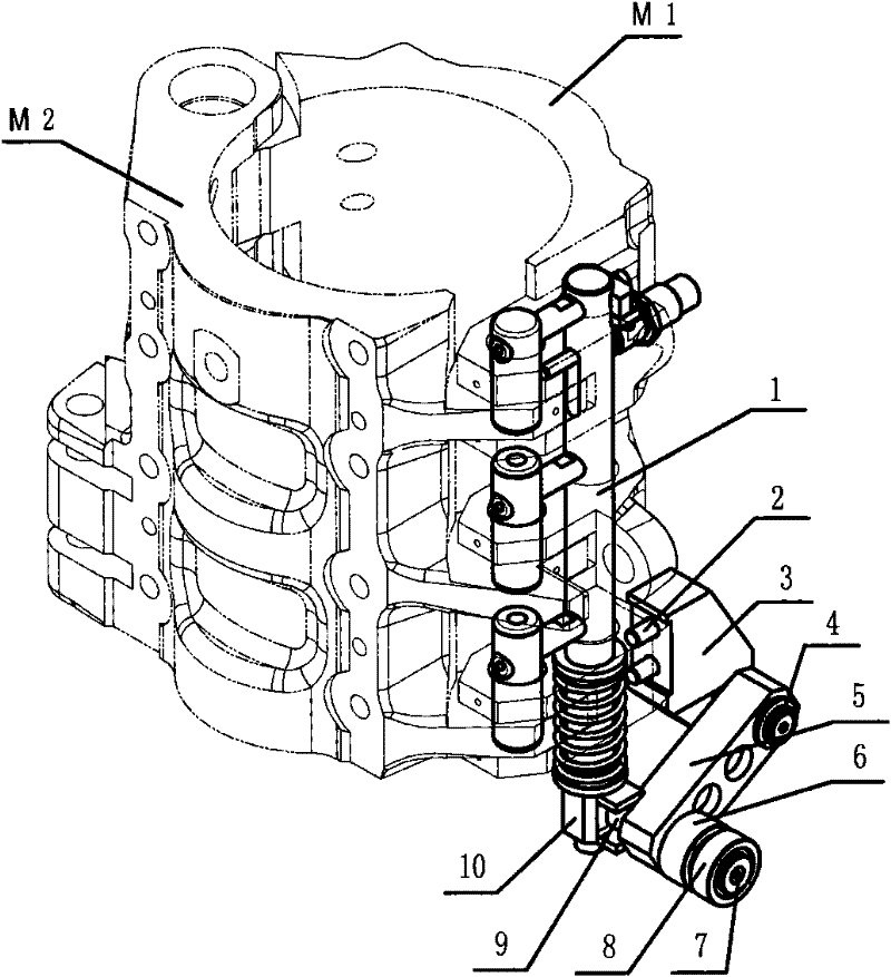
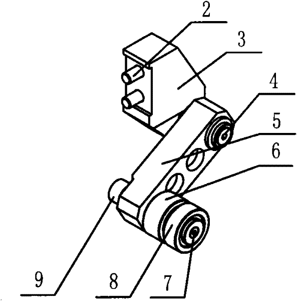
[0017] refer to figure 2 , image 3 , Figure 4 , Figure 5 Shown:

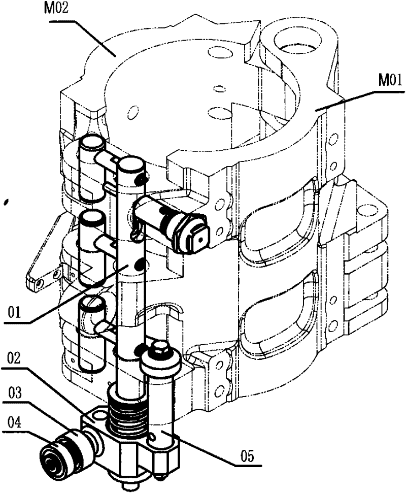
[0018] A toggle device suitable for a fully automatic rotary high-speed blow molding machine to make the clamping shaft assembly (1) go up and down smoothly. And the toggle block (10) controlled by it, the swing arm member includes connecting screw (2), swing arm seat (3), swing arm shaft (4), swing arm (5), roller A (6) , roller shaft (7), roller B (8), toggle wheel (9), the swing arm component is fixed on the formwork M1 by two connecting screws (2) on the swing arm base (3), the swing arm ( 5) is connected together with the swing arm base (3) through the swing arm shaft (4), and can rotate on the swing arm shaft (4), and the other end of the swing arm (5) is equipped with a roller shaft (7), Roller A (6) and Roller B (8) are installed on the roller shaft (7) in turn, an...


PUM


Abstract

The invention discloses a striking device used for smoothly elevating of a mode locked shaft component on a full-automatic rotary type high speed bottle blowing machine. The shape of the device comprises a set of swing components capable of rotating around a swing arm shaft, and a prodding block which is controlled by the set of swing components as well as possesses a raceway on its side surface. A set of guiding shaft mechanism can be omitted after installing the device, so the weight of machine is reduced, rotational inertia and centrifugal force can be reduced as well as the interference effect generated by a dual-shaft movement can be avoided. Because a prodding wheel is rolled in the raceway of the prodding block, so that a reaction force from a mode locked guide rail can be eliminated, the bending deformation of the mode locked shaft can be avoided, the abrasive wear of the mode locked shaft can be mitigated as well as the service life of the mode locked shaft can be prolonged, the smooth elevating of the mode locked shaft component can be guaranteed, thereby a screwing type mold base enables a rapid opening or closing, a more smooth opening or closing of the mold base can be ensured, and the present invention establishes a powerful foundation for development of high speed operation of the full-automatic rotary type bottle blowing machine.

Description

technical field [0001] The patent of the present invention relates to the field of packaging machinery and equipment manufacturing, in particular to a mechanical structure for opening and closing a rotary mold base on a fully automatic rotary high-speed blow molding machine. Background technique [0002] Anyone who is engaged in the bottle blowing industry knows that the function of the mold locking mechanism on the bottle blowing machine is to enable the mold frame to open or close within the set time, so as to ensure that the mold can also be opened or closed at the same time, so as to ensure that the finished bottle can be in the bottle. It is taken out from the cavity of the mold in an instant, and the preform can be sent into the cavity of the mold in an instant, so it is repeated frequently. However, with the implementation of environmental protection measures for energy saving, emission reduction and low-carbon economy, the deteriorating ecological environment forces ...

Claims


Application Information

Patent Timeline
Patent Type & Authority Applications(China)
IPC IPC(8): B29C49/42C03B9/40B29L22/00
Inventor 邹大群吴志刚林世鸿宁远鹏刘玲
Owner GUANGZHOU TECH LONG PACKAGING MACHINERY CO LTD
Why Eureka
Try Eureka