
Battery charging system for hybrid vehicles

A technology of hybrid electric vehicle and charging system, which is applied in the field of battery charging system and can solve problems such as vehicle performance deterioration

Inactive Publication Date: 2011-10-05
GM GLOBAL TECH OPERATIONS LLC
View PDF3 Cites 6 Cited by
  • Summary
  • Abstract
  • Description
  • Claims
  • Application Information

AI Technical Summary

Problems solved by technology

For longer trips, the internal combustion engine is used or used more, which results in poorer vehicle performance

Method used


Image

  • Battery charging system for hybrid vehicles
  • Battery charging system for hybrid vehicles
  • Battery charging system for hybrid vehicles

Examples


Embodiment Construction

[0012] The term "hybrid vehicle" used in this specification includes all hybrid electric vehicles, plug-in hybrid electric vehicles (PHEVs), extended-range electric vehicles (REVs), and the like. Hybrid vehicles include in particular all vehicles with an internal combustion engine (or other secondary power source), whether or not such power source is capable of directly driving the drive wheels or other propulsion components of the vehicle, and which have one or more batteries which Capable of supplying energy to electric motors that drive wheels or other propulsion components.

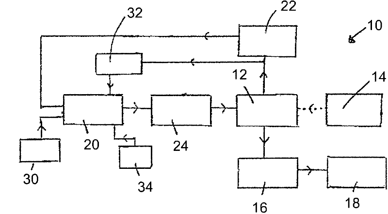
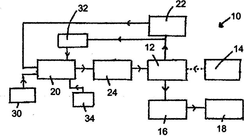
[0013] Referring now to the accompanying drawings, figure 1 A battery charging system 10 for an extended-range electric vehicle is shown. The system is typically installed in a car or other road vehicle. The system includes an accumulator 12 which can be charged by an external power source 14 connected to an eg mains feed.

[0014] The battery 12 powers an electric motor 16 which in turn operates a...


PUM


Abstract

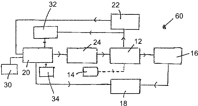
The invention relates to a battery charging system for the hybrid vehicles, which enables the battery of the hybrid vehicle to be charged before travelling. A user-operated switch 30 is provided to enable an engine 20 to operate a generator 24 to charge a battery while the vehicle is parked.

Description

technical field [0001] The present invention relates to a hybrid electric vehicle and more particularly to a battery charging system for a plug-in hybrid vehicle and a range extended electric vehicle. Background technique [0002] Plug-in hybrid vehicles and extended-range electric vehicles have the potential to deliver substantial fuel cost savings to their owners and ultimately reduce dependence on petroleum. . For such vehicles, especially range-extended electric vehicles, the achievable performance is related to the availability of charge in the battery for powering or supplementing the conventional internal combustion engine. Once the battery is depleted, it reduces the performance of the vehicle. For local excursions with layover intervals, the user of the hybrid vehicle has the opportunity to fully charge the vehicle battery from the feeder or other external source between trips. For longer trips, the internal combustion engine is used or used more, which results i...

Claims


Application Information

Patent Timeline
IPC IPC(8): B60K6/32B60L11/18B60L50/10
CPCB60L2240/445B60W30/18054B60W10/26B60L2200/26Y02T10/6217B60L11/126B60K6/46B60L11/123Y02T90/34B60W20/00B60W2540/06Y02T10/7077B60L2240/36Y02T10/7005B60W2510/244B60L2200/12B60L50/61B60L50/62Y02T10/62Y02T10/70Y02T90/40B60K6/20B60L50/10B60W10/06B60W2420/30B60W20/13Y02T10/7072
Inventor 迈克尔·波特
Owner GM GLOBAL TECH OPERATIONS LLC
Learn More