Electric booster brake device for vehicle

A technology of electric power boosting and braking devices, which is applied in the direction of automatic starting devices, braking transmission devices, foot-operated starting devices, etc., can solve the problems that the size of the power assist cannot be effectively adjusted, and there is idle travel, etc., so as to avoid idle travel and avoid The effect of poor stiffness

Inactive Publication Date: 2011-10-05
SHANGHAI HUAPU AUTOMOBILE CO LTD +1
View PDF9 Cites 23 Cited by
  • Summary
  • Abstract
  • Description
  • Claims
  • Application Information

AI Technical Summary

Problems solved by technology

[0005] The present invention mainly aims at the problem that the power boosting size of the existing vacuum booster brake device for automobiles cannot be effectively adjusted, and there is idle travel, etc

Method used


Image

  • Electric booster brake device for vehicle
  • Electric booster brake device for vehicle
  • Electric booster brake device for vehicle

Examples


Embodiment 1

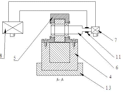
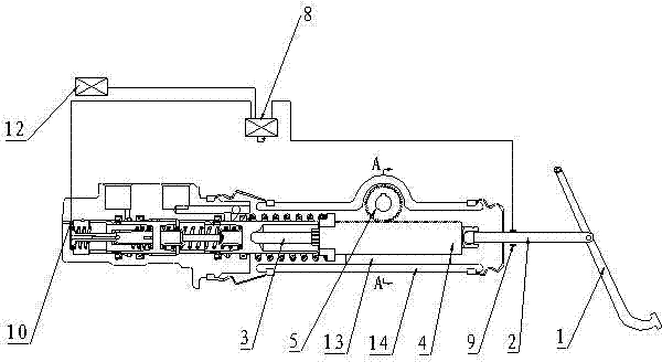
[0017] like figure 1 As shown, a kind of automobile electric power-assisted braking device, pedal 1 is hinged with input force push rod 2, and input force push rod 2 is provided with a speed sensor 9, and speed sensor 9 is connected with electronic control unit 8 on the car. The input force push rod 2 and the ball seat are connected at three points by riveting, and the ball seat and the rack 4 are threaded. The rack 4 below is provided with a rack 4 chute, and the rack 4 and the rack 4 chute are slidably connected and coated with grease to reduce sliding friction. There is also a gear 5 meshing with the rack 4 above the rack 4, the gear 5 is connected with the DC motor belt reducer assembly 7 through the transmission shaft 6, and the DC motor belt reducer assembly 7 is powered by the vehicle battery In operation, the DC motor belt reducer assembly 7 is connected with the electronic control unit 8 . The rack 4 is connected with the output force push rod 3, and a return spring...

Embodiment 2

[0023] The structure of this embodiment is basically the same as that of Embodiment 1, the difference is that this embodiment is equipped with an ultrasonic distance measuring probe 12 at the front end of the vehicle, and the ultrasonic distance measuring probe 12 is connected to the electronic control unit 8 . When the car is running, the electronic control unit 8 continuously sends instructions to the ultrasonic distance measuring probe 12 to order the ultrasonic distance measuring probe 12 to continuously detect the road condition information in front of the vehicle. According to the pre-programmed program of the electronic control unit 8, when the ultrasonic When the ranging probe 12 detects an obstacle within a certain distance ahead, such as: 50 meters or 20 meters, the electronic control unit 8 automatically starts the braking program, and the electronic control unit 8 commands the DC motor to start. Complete the braking task according to the electric power-assisted brak...


PUM


Abstract

The invention relates to a brake device for a vehicle, in particular to an electric booster brake device. The electric booster brake device for the vehicle comprises a pedal, an input force push rod connected with the pedal, a booster connected with the input force push rod, an output force push rod connected with the booster and a master cylinder connected with the output force push rod. The booster comprises racks connected between the input force push rod and the output force push rod, a gear engaged with the racks, a direct-current motor belt speed reducer assembly connected with the gear via a transmission shaft, an electronic control unit (ECU) and a speed sensor connected to the input force push rod; and the speed sensor is connected with the ECU which is connected with the direct-current motor belt speed reducer assembly. The electric booster brake device for the vehicle has the characteristics that the brake boost can be automatically adjusted according to requirements and has an intelligent automatic brake mode, idle stroke and poor rigidity are effectively avoided, and the like.

Description

technical field [0001] The invention relates to an automobile braking device, in particular to an electric power-assisted braking device. Background technique [0002] With the improvement of people's requirements for automobile safety, people's requirements for automobile braking devices are also constantly improving. Most of the boosters in the existing automobile braking devices use vacuum boosters. The vacuum booster is the core component of the vacuum booster servo braking system. It uses the pressure difference between the vacuum of the engine intake pipe and the atmosphere to play a boosting role. When the engine is started, the engine sucks the air from the front chamber and the rear chamber of the vacuum booster through the vacuum hose. At this time, it is in the open state, the atmospheric valve is in the closed state at this time, the front chamber and the rear chamber are connected, there is no pressure difference between the two chambers, and the vacuum booster...

Claims


Application Information

Patent Timeline
IPC IPC(8): B60T13/02B60T13/74B60T7/04B60T7/12
Inventor 郝晓宏金先扬江明李书福杨健余卫
Owner SHANGHAI HUAPU AUTOMOBILE CO LTD
Why Eureka
Try Eureka