Split type vibration isolating device and application thereof

A split-type, vibration-isolating technology, applied in the directions of roads, building components, tracks, etc., can solve the problems of inability to realize stock production, different sizes of connecting sleeves, unable to accommodate connecting sleeves, etc., so as to improve the rapid response of supply. Ability, compact and reasonable structure, the effect of shortening the processing cycle

Active Publication Date: 2011-10-05
尹学军 +1
View PDF0 Cites 26 Cited by
  • Summary
  • Abstract
  • Description
  • Claims
  • Application Information

AI Technical Summary

Problems solved by technology

In the actual application process, on the one hand, due to the limitation of many factors such as space, cost and environment, the height reserved for the floating plate in many cases cannot accommodate a larger connecting sleeve, so the floating plate cannot be used; on the other hand , the height of the floating plate is often determined very late in the engineering design. Due to the change of the thickness of the floating plate, the size of the connecting sleeves of various heights is different, and stock production cannot be realized, so the delivery time is long
Especially when design changes are encountered during construction, because the corresponding period is long, it is easy to affect the construction progress

Method used


Image

  • Split type vibration isolating device and application thereof
  • Split type vibration isolating device and application thereof
  • Split type vibration isolating device and application thereof

Examples


Embodiment 1

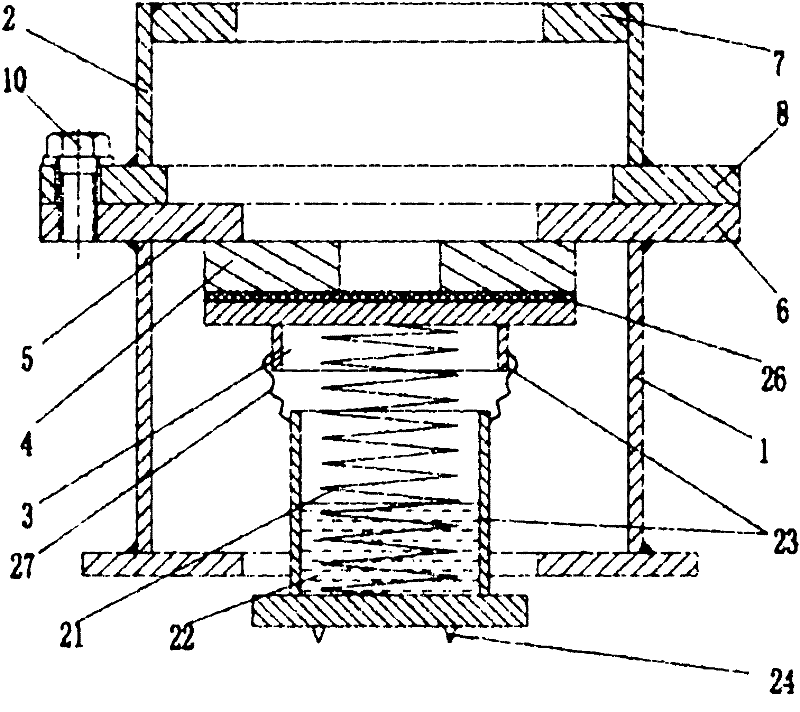
[0035] like figure 1 The shown split type vibration isolation device of the present invention includes a lower sleeve 1, an upper sleeve 2, a spring vibration isolator 3 and a gasket 4, wherein, the upper part of the lower sleeve 1 is provided with a support stopper 5, and for simplifying the structure, the The supporting stopper 5 is integrated with the connecting flange 6 at the top of the lower sleeve, and the upper part of the upper sleeve 2 is provided with a jacking stopper 7 . The lower sleeve 1 and the upper sleeve 2 are coupled together by means of the bolts 10 arranged between the connecting flange 6 at the top end of the lower sleeve 1 and the connecting flange 8 at the bottom end of the upper sleeve 2 . The thickness of the lower sleeve 1 is adapted to the thickness of the floating plate 9 .

[0036]The spring vibration isolator 3 includes a spring housing and a spring 21. The spring 21 is located in the spring housing 23 and is a helical spring with suitable rigi...

Embodiment 2

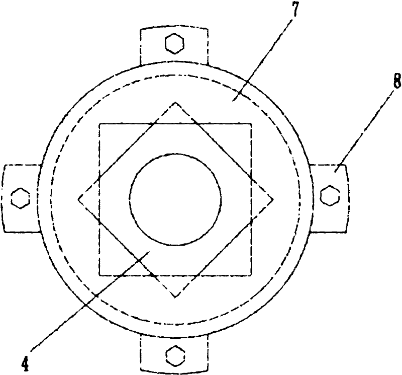
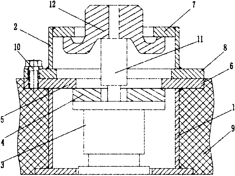
[0042] like figure 1 , Figure 5 Figure 6 As shown, the difference from Embodiment 1 is that the upper sleeve 2 and the lower sleeve 1 are fixedly connected and preset in the floating plate 9. After the jacking is completed, a dustproof cover is correspondingly installed above the upper sleeve 2. 14 and gasket 15. Of course, the dustproof cover 14 can also be completely embedded in the upper sleeve 2, which is more attractive in appearance.

[0043] When in use, the lower sleeve 1 can be standardized and produced in stock, and the upper sleeve 2 can be processed according to the actual thickness of the floating plate 9 before delivery, and the height of the connecting sleeve can be quickly matched in the factory or on the construction site, so that there is It is beneficial to further shorten the processing cycle, improve construction efficiency, and can better meet the vibration isolation requirements of floating slabs with different thicknesses or floating slabs with con...

Embodiment 3

[0045] like Figure 7 As shown, the difference from Embodiment 1 is that the coupling flange at the bottom of the upper sleeve 2 is eliminated, and the pin holes provided on the side walls of the lower sleeve 1 and the upper sleeve 2 are used to connect the two together through pins 16 .

[0046] The structure of the upper sleeve 2 adopting this connection method is simpler, less material is used, and the cost is correspondingly lower. The space above the supporting block 5 of the lower sleeve 1 can be used to place a dust cover (not shown in the figure) after the upper sleeve 2 is removed, and the space utilization is more compact and more reasonable. Of course, threaded holes can also be provided, and bolts can be used instead of pins to realize the connection.

[0047] In addition to the cooperating connection between the pin holes and the pin bolts, it is also possible to set the pin bolts on the side walls of the upper and lower sleeves, and the upper and lower sleeves a...


PUM


Abstract

The invention belongs to the control field of vibration and noise, and particularly relates to application of a vibration isolating device of a railway vehicle. The vibration isolating device comprises a linkage sleeve and a spring vibration isolator; the linkage sleeve is provided with a supporting stopper block and a jacking stopper block; the linkage sleeve consists of an upper sleeve and a lower sleeve; a detachable linkage mechanism is arranged between the upper sleeve and the lower sleeve; the supporting stopper block is arranged at the upper part of the lower sleeve; the jacking stopper block is arranged at the lower part of the upper sleeve. The split type vibration isolating device solves the problem that the linkage sleeve has a large size caused by the preset jacking installation space in the current vibration damper and cannot be applied to the thinner floating slabs of a railway; the split type vibration isolating device disclosed by the invention has a compact and reasonable structure and low cost, enlarges application range of the vibration isolating device under a track bed, has high practicability and gives considerations to both the economic effect and the environment protecting effect. The split type vibration isolating device disclosed by the invention is applicable to the vibration isolation of floating plates, building floors or equipment bases, in particular to the vibration isolation of metro railways, and can be widely applied to the vibration isolations of rail traffic fields such as railways, urban railways, elevated railways and high speed railways.

Description

technical field [0001] The invention belongs to the field of vibration and noise control, and in particular relates to a vibration isolation device for alleviating the adverse effects caused by the vibration and noise emitted during the operation of rail vehicles or reducing the vibration of building components and equipment foundations. Background technique [0002] The traditional rail transit structure will generate large vibration and noise when the vehicle is running. These vibration and noise not only affect the nearby buildings and equipment, but may also cause harm to the human body. Therefore, for urban areas with relatively concentrated population and buildings, the problem of vibration and noise reduction of rail transit is particularly important. Existing vibration reduction measures are divided into three levels: under-rail vibration isolation, under-pillar vibration isolation, and under-ballast bed vibration isolation according to the different nodes involved i...

Claims


Application Information

Patent Timeline
Patent Type & Authority Applications(China)
IPC IPC(8): E01B19/00E04B1/98
Inventor 尹学军汉斯·格约克·瓦格纳
Owner 尹学军
Why Eureka
Try Eureka