Positioning method of transverse wave TOFD (Time of Flight Diffraction) defect

A positioning method, transverse wave technology, applied in the use of sound waves/ultrasonic waves/infrasonic waves to analyze solids and other directions, can solve problems such as accurate positioning of workpieces, achieve accurate positioning, high precision, and avoid scattering signal interference

Inactive Publication Date: 2011-10-05
BEIJING INSTITUTE OF TECHNOLOGYGY
View PDF3 Cites 23 Cited by
  • Summary
  • Abstract
  • Description
  • Claims
  • Application Information

AI Technical Summary

Problems solved by technology

[0005] In order to overcome the fact that the existing ultrasonic time-of-flight diffraction method (TOFD) cannot accurately locate the defect in the workpiece through a single linear scan, the present invention proposes a shear wave TOFD defect positioning method. This method uses a pair of shear wave probes and simultaneously uses the longitudinal wave and shear wave scattering of the defect signal to achieve three-dimensional localization of defects

Method used


Image

  • Positioning method of transverse wave TOFD (Time of Flight Diffraction) defect
  • Positioning method of transverse wave TOFD (Time of Flight Diffraction) defect
  • Positioning method of transverse wave TOFD (Time of Flight Diffraction) defect

Examples


Embodiment Construction

[0027] The specific embodiment of the present invention is described in detail below:

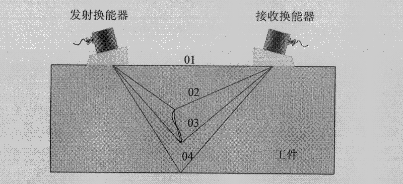
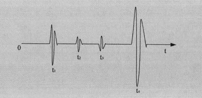
[0028] In order to verify the feasibility of the above-mentioned shear wave TOFD defect location method, a test block containing defects was designed. The aluminum plate test block was artificially flawed by EDM. According to Image 6 As shown in , arrange a pair of shear wave transducers on the surface of the workpiece to be tested, and let the transducers scan along the centerline of the plate, and the obtained A-scan signal and B-scan image are as follows: Figure 7 As shown, the shear wave scattering signal in the B-scan image is strong, and the longitudinal wave scattering signal is relatively weak, but it can still be identified. Then, using the above-mentioned shear wave TOFD defect positioning method, we conduct a positioning study on the artificial defect and compare it with its actual position. The measurement results show that the defect location error is less than 3%, which veri...


PUM


Abstract

In the ultrasonic nondestructive testing field, the traditional time of flight diffraction (TOFD) is used for finding defects of a welding line by only using a longitudinal wave scattering signal; because the type of used signals is single, the three-dimensional positioning of the internal defect of the welding line cannot be realized by the single linear scanning. Aiming the problem, the invention provides a transverse wave TOFD detecting method; one pair of transverse wave probes are used for performing the single linear scanning along the welding line; at the same time, the longitudinal wave and the transverse wave scattering signals of the internal defect of the welding line are used for analyzing to point out that the defect is located on an elliptic trajectory determined by the transverse wave scattering signal and is also located on a circular trajectory determined by the longitudinal wave scattering signal, thus the three-dimensional positioning of the internal defect of the material can be realized by obtaining the intersecting point of the two curves.

Description

1. Technical field [0001] The invention relates to the field of ultrasonic non-destructive testing, and proposes a shear wave TOFD defect positioning method, which uses a pair of shear wave probes to perform a single linear scan along both sides of the weld, and uses the longitudinal wave and shear wave scattering signals of the defect to find defects in the weld. And accurately locate the defect. 2. Background technology [0002] Ultrasonic time of flight diffraction (TOFD for short) can efficiently detect and locate internal cracks in components, and is gradually being promoted and applied in the industrial field. When ultrasonic waves are incident on the surface of defects (air holes, cracks, inclusions, etc.), the sound wave energy will form scattered waves at the corners of the defects, and the scattered energy spreads in all directions, so scattered echoes can be received from almost all directions. Ultrasonic diffraction time-of-flight method is an ultrasonic non-des...

Claims


Application Information

Patent Timeline
Patent Type & Authority Applications(China)
IPC IPC(8): G01N29/04
Inventor 赵新玉徐春广肖定国孙向辉周世圆郝娟孟凡武潘勤学
Owner BEIJING INSTITUTE OF TECHNOLOGYGY
Why Eureka
Try Eureka