Rotating machine

A technology for rotating electrical machines and rotors, which is applied in electrical components, electromechanical devices, and prevention/reduction of eddy current losses in winding heads, etc. It can solve the problems of large weight, large eddy current losses, and heavy powder core weight, etc., to reduce losses Effect

Inactive Publication Date: 2011-10-05
HITACHI LTD
View PDF7 Cites 13 Cited by
  • Summary
  • Abstract
  • Description
  • Claims
  • Application Information

AI Technical Summary

Problems solved by technology

[0022] In the above-mentioned existing examples, there is a problem that losses generated in the clamping part and its shielding part are large
In the magnetic shield member using steel plates described in Patent Document 1, the eddy current loss of the shield member itself due to the magnetic flux flowing in from the stacking direction is large.
In addition, as in Patent Document 2, even if a conductive plate is used, it is necessary to cover all surfaces of the clamp member with a conductive plate, which requires a large weight.
In Patent Document 3, the dust core used as the magnetic shielding member is heavy, and in Patent Document 4, there is a problem that the magnetic shielding member has little effect of attracting magnetic flux.

Method used


Image

  • Rotating machine
  • Rotating machine
  • Rotating machine

Examples


Embodiment 1

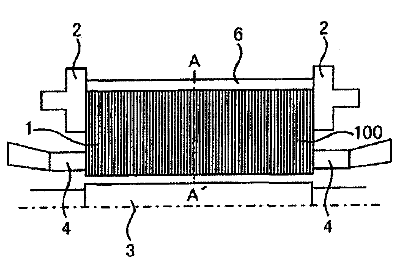
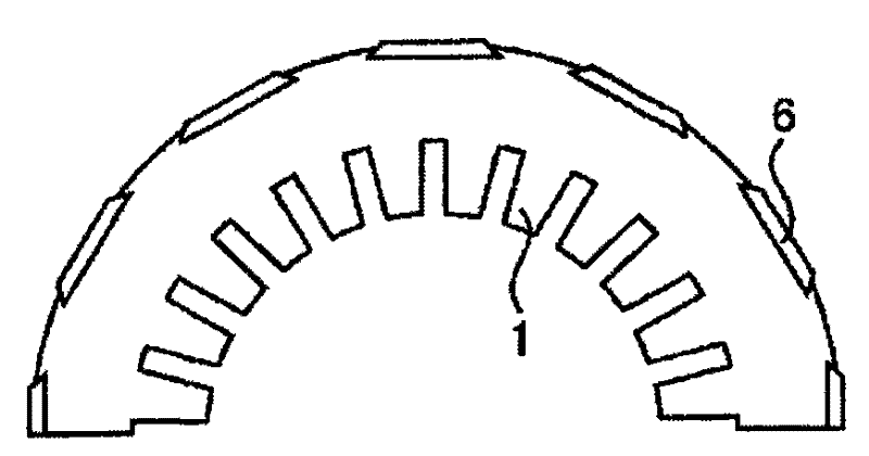
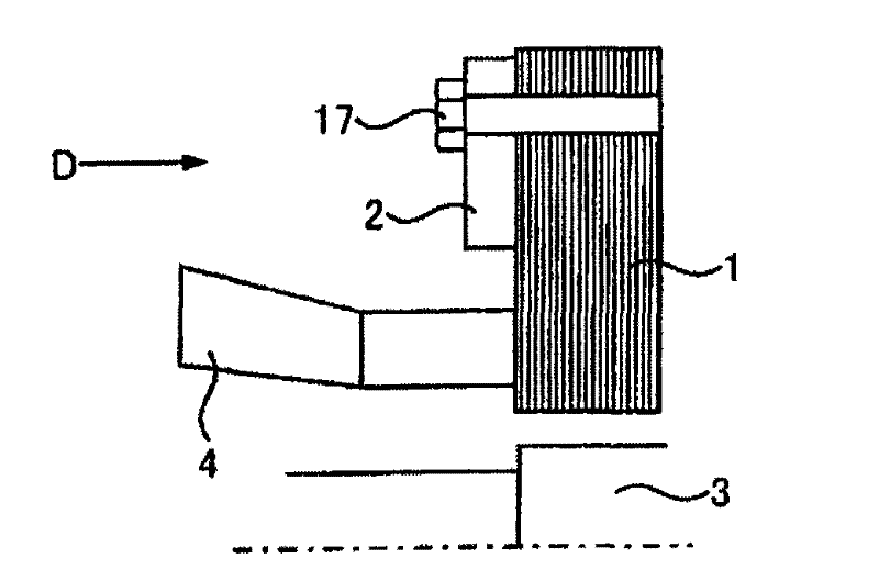
[0088] Figure 5 It is a figure which shows the stator end part of the turbine generator which is an example of the rotating electric machine to which this invention was applied.

[0089] As shown in the figure, in this embodiment, the clamping member 2 fastens the stator core 1 from both ends along the lamination direction of the electromagnetic steel sheets, and the magnetic shielding member is attached to the clamping member 2. The magnetic shielding As components, a laminated steel plate cylinder 7 laminated in a cylindrical shape around the rotor shaft, and a dust core material 8 obtained by compression-molding insulating-coated magnetic powder were used. The magnetic shielding member is disposed on the outer diameter side of the stator winding 4 so as to cover the side surface and the inner diameter surface of the clamping member 2, and when the magnetic shielding member is attached to the clamping member 2, there Between the laminated steel plate cylinder 7 and the pow...

Embodiment 2

[0123] Such as Figure 9 Covering the surface of the powder magnetic core material 8 of Example 1 with resin as shown, or placing each powder magnetic core material 8 in a resin case 9 for accommodating a single powder magnetic core material can prevent the dust from being crushed. Splash of iron dust from powder magnetic core. Additionally, if Figure 10 and Figure 11 As shown, by accommodating a plurality of powder magnetic core materials 8 in a resin case 19 for accommodating a plurality of powder magnetic core materials, the number of parts can be reduced and the installation becomes easy.

[0124] In addition, in order to prevent the powder magnetic core member 8 from moving in the housing 19, as Figure 12 As shown, a slot 18 can also be provided in the housing 19 .

Embodiment 3

[0126] Such as Figure 13 As shown, in this embodiment, an end duct spacer (end duct spacer) 5 is disposed between the stator core 1 and the clamping member 2 in the axial direction.

[0127] In this embodiment, a ventilation pipe for cooling is formed between the stator core 1 and the clamping part 2 through the end pipe spacer 5, which improves the cooling performance.

[0128] Additionally, if Figure 14 As shown, a groove is provided in the circumferential direction of the end surface of the end tube spacer 5, so that the powder magnetic core piece 8 protrudes into the groove along the circumferential direction, so that the magnetic flux entering the clamping part 2 from the end tube spacer 5 can be Attraction to the powder magnetic core material 8 can further reduce the loss of the clamping member 2 .


PUM


Abstract

The invention provides an electric rotating machine which is capable of reducing losses that occur in clamping plates and their shield. The electric rotating machine includes a rotor formed with field winding wound around a rotor core, a stator placed opposite to the rotor at a predetermined space and formed with stator winding wound around a stator core formed by stacking multiple magnetic steelsheets in the axial direction, clamping plates clamping and retaining the stator core from both axial end parts thereof in the stacking direction of the magnetic steel sheets, and a magnetic shield placed around the clamping plates to shield flux leakage flowing into the clamping plates, and the magnetic shield is formed of a cylinder of stacked steel sheets stacked in a form of a cylinder about the rotor shaft and powder magnetic core segments and powder magnetic core segments having portions which are stuck to the cylinder of stacked steel sheets on the stacking cross section, and arranged to cover side surfaces and an inner surface of radial direction of the clamping plates.

Description

technical field [0001] The present invention relates to a rotating electrical machine, for example, to a rotating electrical machine suitable for a structure in which a stator core used in a large-sized rotating electrical machine such as a turbo generator is formed by laminating a plurality of electromagnetic steel sheets, and is clamped from an axial end by a clamping member. The stator core is fastened. Background technique [0002] A conventional example will be described taking a turbo generator as an example of a large rotating electrical machine. [0003] figure 1 and figure 2 Shows the schematic structure of a turbo generator. The turbine generator shown in this figure is mainly composed of a rotor 3 formed by winding a field winding on a rotor core, and a stator 100 arranged to face the rotor 3 with a predetermined gap therebetween. This stator 100 is formed by winding a stator winding 4 around a stator core 1 . [0004] The stator core 1 is formed by punching...

Claims


Application Information

Patent Timeline
Patent Type & Authority Applications(China)
IPC IPC(8): H02K1/06H02K1/18
CPCH02K2213/03H02K3/42H02K1/12
Inventor 吉田润中原明仁小村昭义
Owner HITACHI LTD
Why Eureka
Try Eureka