
Liquid crystal display device and method for manufacturing liquid crystal display device

A technology of liquid crystal display device and liquid crystal layer, which is applied in nonlinear optics, instruments, optics, etc., and can solve problems such as narrow viewing angle

Inactive Publication Date: 2011-10-05
SHARP KK
View PDF12 Cites 5 Cited by
  • Summary
  • Abstract
  • Description
  • Claims
  • Application Information

AI Technical Summary

Problems solved by technology

However, the conventional twisted nematic (TN type) and super twisted nematic (STN type) liquid crystal display devices have the disadvantage of narrow viewing angles, and various technological developments are being made to solve this problem.

Method used


Image

  • Liquid crystal display device and method for manufacturing liquid crystal display device
  • Liquid crystal display device and method for manufacturing liquid crystal display device
  • Liquid crystal display device and method for manufacturing liquid crystal display device

Examples


Embodiment Construction

[0061] Hereinafter, embodiments of the present invention will be described with reference to the drawings. In addition, this invention is not limited to the following embodiment.

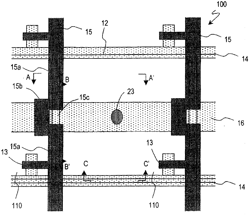
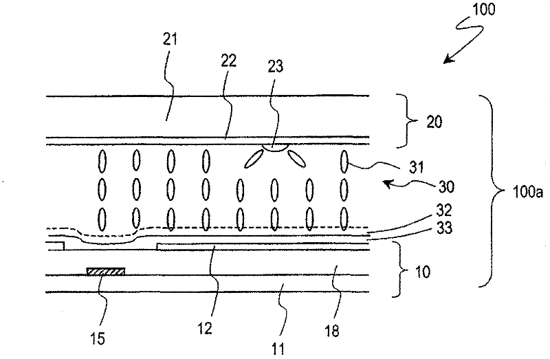
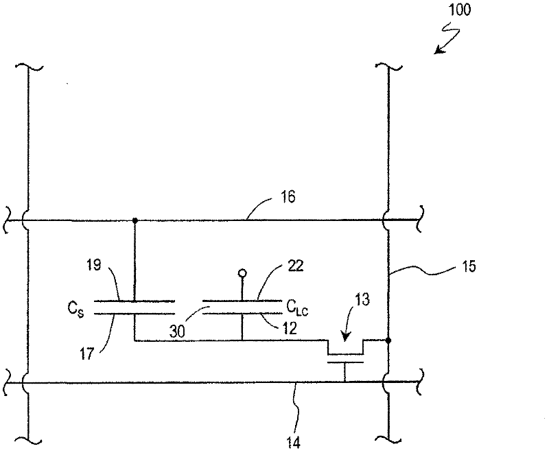
[0062] figure 1 , figure 2 and image 3 A liquid crystal display device 100 in the CPA mode of this embodiment is shown. figure 1 is a plan view schematically showing a region corresponding to one pixel of the liquid crystal display device 100, figure 2 is along figure 1 The cross-sectional view along line A-A' of , shows a state where no voltage is applied to the liquid crystal layer (or a state where a voltage lower than the threshold voltage is applied). in addition, image 3 An equivalent circuit of one pixel of the liquid crystal display device 100 is shown.

[0063] like figure 1 and figure 2 As shown, the liquid crystal display device 100 includes a liquid crystal display panel 100a with a figure 1 A plurality of pixels 110 arranged in a matrix in the up-down direction (firs...


PUM


Abstract

High quality display is provided by reducing display nonuniformity in a liquid crystal display device. The liquid crystal display device is provided with: a TFT substrate (10) having a signal wiring line (15), which has a plurality of pixels (110) arranged in a first direction and a second direction, extends in the first direction, and supplies a TFT (13) with display signals, and a scanning wiring line (14), which extends in the second direction and supplies the TFT (13) with gate signals; a facing substrate (20) having counter electrodes; a vertically aligned liquid crystal layer (30) arranged between the substrates; and a vertical alignment film (33). The signal wiring line (15) and / or the scanning wiring line (14) has two linear sections (15a) which linearly extend in the first direction or the second direction on the boundary between adjacent two pixels, and a bent section (15b) which is arranged between the two linear sections and extends outside of the extending lines from the two linear sections. At the time of forming an alignment sustaining layer in the liquid crystal display device of a PSA system, liquid crystal molecules on the signal wiring line and / or the scanning wiring line can be aligned stably and in the more desirable direction.

Description

technical field [0001] The present invention relates to a vertical alignment type liquid crystal display device having a vertical alignment layer. Background technique [0002] In recent years, thin and lightweight liquid crystal display devices have been used as display devices for monitors of personal computers and display units of portable information terminal devices. However, conventional twisted nematic (TN type) and super twisted nematic (STN type) liquid crystal display devices have a disadvantage of a narrow viewing angle, and various technologies are being developed to solve this problem. [0003] An alignment split type liquid crystal display device having a vertical alignment type liquid crystal layer is known as a liquid crystal display device having improved viewing angle characteristics. Such a liquid crystal display device is called a VA (Vertical Alignment: vertical alignment) mode liquid crystal display device. As an example of a VA mode liquid crystal di...

Claims


Application Information

Patent Timeline
Patent Type & Authority Applications(China)
IPC IPC(8): G02F1/1368G02F1/1337
CPCG02F1/133707G02F1/136286G02F1/136213
Inventor 永田尚志
Owner SHARP KK
Learn More