

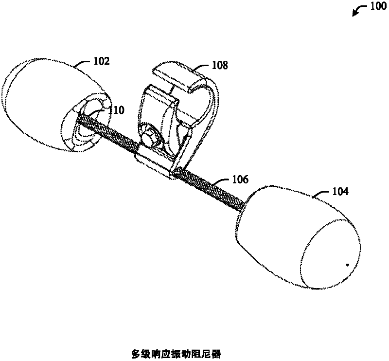
Multi-response vibration damper assembly
A technology of damping system and inserts, which is applied in the direction of mechanical vibration attenuation devices, overhead lines/cable equipment, etc., can solve problems such as not so effective, and achieve the effect of reducing vibration
- Summary
- Abstract
- Description
- Claims
- Application Information
AI Technical Summary
Problems solved by technology
Method used
Image

Examples
Embodiment Construction
[0026] The invention will now be described with reference to the drawings, in which like reference numerals are used to designate like parts. In the following description, for purposes of explanation, numerous specific details are set forth in order to provide a thorough understanding of the present invention. It is evident, however, that the invention may be practiced without these specific details. In other instances, well-known structures and devices are shown in block diagram form in order to facilitate describing the present invention.
[0027] Aeolian vibrations are high frequency, low amplitude motions most often caused by smooth laminar wind passing through a transmission line. When a wire or cable is exposed to this wind, a phenomenon known as "vortex" or "eddy current" causes vibrations on the line. Wind-induced vibration can cause hardware to fail, fatigue, wear, and eventually lead wires to failure. Vibration dampers are commonly used to control wind-induced vib...
PUM
 Abstract
Description
Claims
Application Information