Full-automatic punching flanging device

A fully automatic punching technology, applied in the field of mechanical processing, can solve the problems of high production cost, poor hole pitch accuracy, and low work efficiency, and achieve the effects of low production cost, high work efficiency, and high hole pitch accuracy

Active Publication Date: 2013-03-06
JIANGXI AVONFLOW HVAC TECH CO LTD
View PDF4 Cites 2 Cited by
  • Summary
  • Abstract
  • Description
  • Claims
  • Application Information

AI Technical Summary

Problems solved by technology

In the prior art, two processes are required for punching and flanging on the same workpiece, punching and flanging the pipe respectively, and there are also devices capable of punching and flanging the pipe at the same time, but it can only be punched at one time. One hole, and then drilling another hole requires manual distance measurement, which is prone to the problem of poor hole distance accuracy, and the operation is cumbersome, high production cost, and low work efficiency

Method used


Image

  • Full-automatic punching flanging device
  • Full-automatic punching flanging device
  • Full-automatic punching flanging device

Examples


Embodiment 1

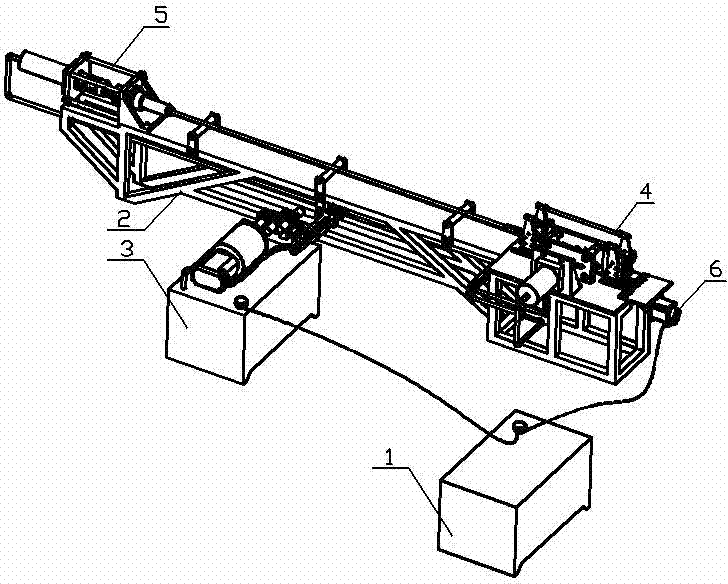
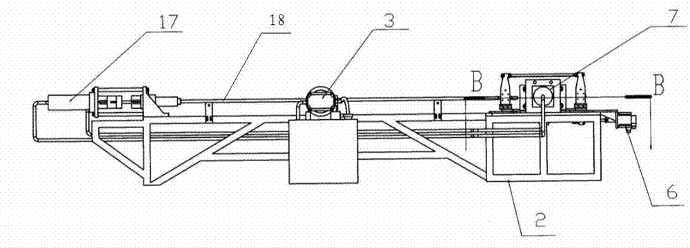
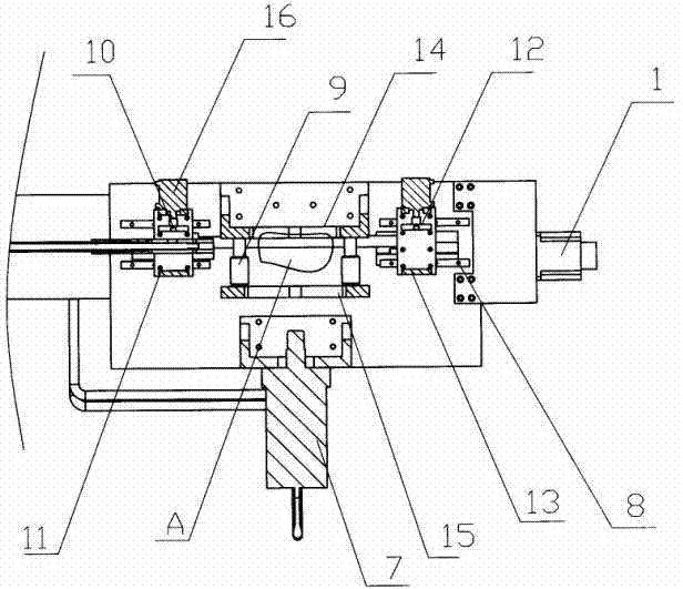
[0021] The fully automatic punching and flanging device is composed of a console 1, a frame body 2, a fuel tank 3, a front cylinder group 4, a rear cylinder group 5 and a motor 6, and the front cylinder group 4 and the rear cylinder group 5 are respectively installed on two sides of the frame body 2. The oil tank 3 is installed outside the frame body 2 to provide power for the front oil cylinder group 4 and the rear oil cylinder group 5 respectively. The motor 6 is installed outside the frame body 2 at the end of the front oil cylinder group 4. The console 1 is connected with the oil tank 3 and the motor 6 respectively. connect. The front oil cylinder group 4 is composed of front oil cylinder 7, guide rail 8, pipe frame 9, left upper clamping die 10, left lower clamping die 11, right upper clamping die 12, right lower clamping die 13, upper female die 14, lower female die Die 15, switch 16 is formed, and described guide rail 8 is fixed on the frame body 2, and upper left clamp...

Embodiment 2

[0024] The section of the flanging punch 23 is stepped, and other structures are the same as those in the first embodiment.


PUM


Abstract

The utility model relates to a fully automatic punching and flanging device, which relates to a compound device for punching and flanging a workpiece. The fully automatic punching and flanging device is composed of a console, a frame, a fuel tank, a front cylinder group, a rear cylinder group and a motor. It is characterized in that: the front cylinder group and the rear cylinder group are respectively installed at both ends of the Outside the frame, power is provided for the front oil cylinder group and the rear oil cylinder group respectively. The motor is installed on the outside of the end frame body of the front oil cylinder group, and the console is connected with the fuel tank and the motor respectively. The beneficial effects of the utility model are: the utility model designs the flanging punch to have a stepped or trapezoidal cross-section, which can complete the punching and flanging process at one time, with precise moving distance and high precision of the hole distance, and can continuously process the pipe. Punching and flanging, simple operation, high work efficiency and low production cost.

Description

technical field [0001] The invention relates to the field of mechanical processing, in particular to a composite device for punching and flanging workpieces. Background technique [0002] In industrial production, some products need to process many holes continuously on the surface of the pipe, and have different requirements for the hole distance. According to the needs, some pipes need to be flanged outward after drilling. In the prior art, two processes are required for punching and flanging on the same workpiece, punching and flanging the pipe respectively, and there are also devices capable of punching and flanging the pipe at the same time, but it can only be punched at one time. One hole, and then another hole needs manual distance measurement, which is prone to the problem of poor hole pitch accuracy, and the operation is cumbersome, the production cost is high, and the work efficiency is low. Contents of the invention [0003] The object of the present invention ...

Claims


Application Information

Patent Timeline
Patent Type & Authority Patents(China)
IPC IPC(8): B21D35/00B21D28/28B21D19/12
Inventor 吴剑军
Owner JIANGXI AVONFLOW HVAC TECH CO LTD
Why Eureka
Try Eureka