Corner roller for turning device of belt type conveyor

A technology of belt conveyor and turning device, which is applied to conveyor objects, transportation and packaging, rollers, etc., can solve the problems of large local stress of conveyor belt and friction damage of conveyor belt.

Inactive Publication Date: 2012-12-19
HENAN POLYTECHNIC UNIV
View PDF1 Cites 0 Cited by
  • Summary
  • Abstract
  • Description
  • Claims
  • Application Information

AI Technical Summary

Problems solved by technology

However, practice has proved that the method of arranging small idlers cannot completely solve the problem of large local stress on the conveyor belt because there is always a space between the end faces of adjacent small idlers and there is an angle between the axes.
The small idlers with non-linear busbars will also cause friction damage to the conveyor belt due to the unequal linear speed of each point in contact with the conveyor belt

Method used


Image

  • Corner roller for turning device of belt type conveyor
  • Corner roller for turning device of belt type conveyor

Examples


Embodiment Construction

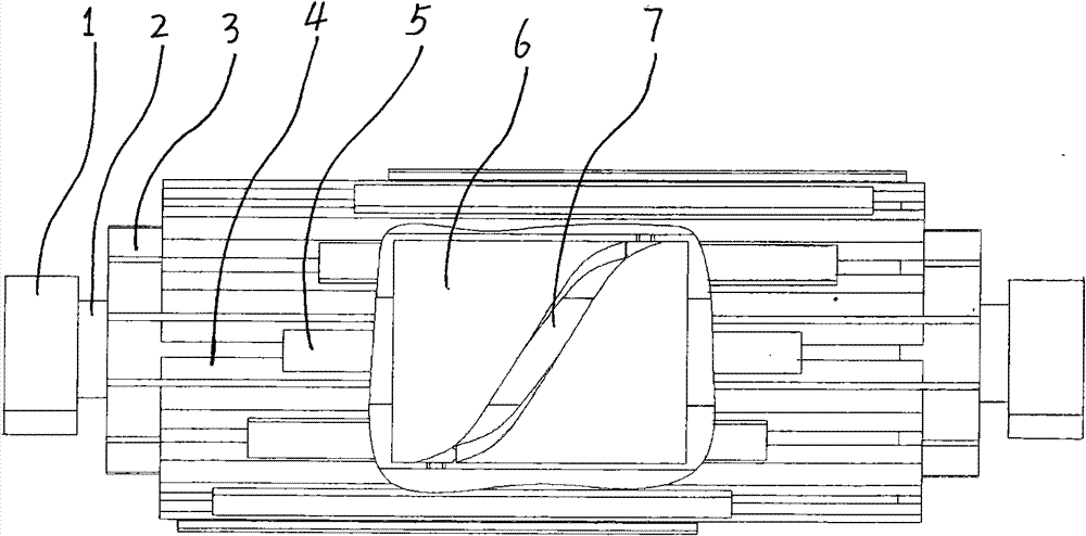
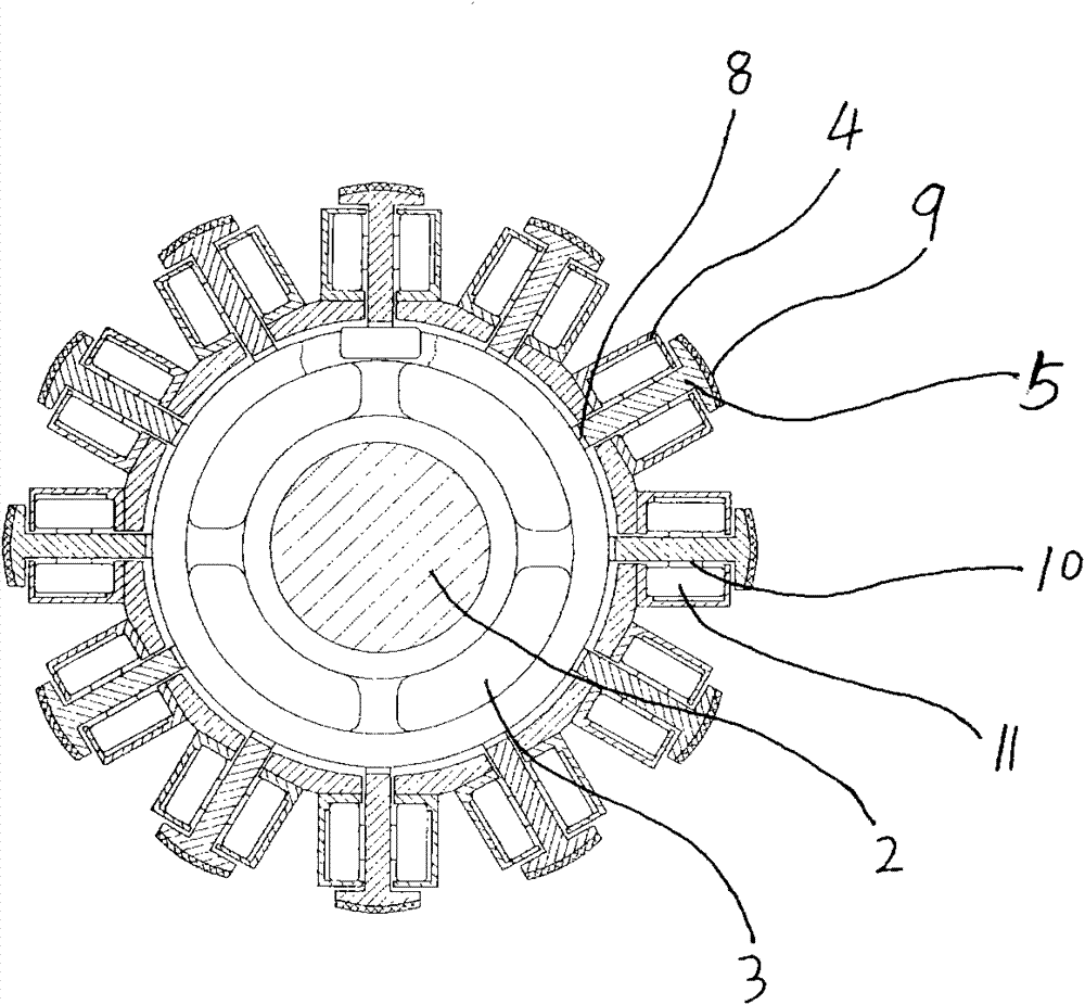
[0010] Depend on figure 1 , figure 2 It can be seen that the present invention includes: a shaft frame 1 , a fixed mandrel 2 , a rotating cylinder 3 , a guide rail 4 , a conveyor belt support 5 , and a hollow cylindrical cam 6 . The fixed mandrel 2 is fixed by the shaft brackets 1 at both ends, the fixed mandrel is fixed by the shaft brackets and cannot rotate, and the rotating cylinder 3 is supported on the fixed mandrel 2 coaxially. A hollow cylindrical cam 6 is arranged between the rotating cylinder 3 and the fixed mandrel 2, the hollow cylindrical cam is concentrically fixed in the middle of the fixed mandrel 2, the hollow cylindrical cam is fixed relative to the fixed mandrel, and the rotating cylinder 3 is fixed relative to the fixed center. The shaft can be turned. An oblique closed-loop cam groove 7 is arranged on the hollow cylindrical cam 6, and a number of guide rails 4 are evenly distributed in the axial direction around the surface of the rotating cylinder 3, a...


PUM


Abstract

The invention discloses a corner roller for a turning device of a belt type conveyor, comprising shaft brackets, a fixed mandrel, a rotating roller body, guide rails, conveyor belt supporting pieces and a hollow cylindrical cam, wherein the fixed mandrel is fixed by the shaft brackets at two ends; the rotating roller body is coaxially supported on the fixed mandrel; the hollow cylindrical cam is arranged between the rotating roller body and the fixed mandrel and is concentrically fixed in the middle part of the fixed mandrel; an inclined closed-loop cam slot is arranged on the hollow cylindrical cam; a plurality of guide rails are uniformly arranged on the periphery of the surface of the rotating roller body at intervals along the axial direction; the matched conveyor belt supporting pieces are arranged on the guide rails; and pushing pieces are fixed at the lower parts of the conveyor belt supporting pieces and are positioned in the cam slot. A roller is passed through the lower of the conveyor belt supporting pieces, and idler wheels located in the guide rail are respectively arranged at two ends of the roller. The invention has the characteristics of uniformity in stress, smaller friction loss, better multi-turning angle adaptability, and the like.

Description

Technical field: [0001] The invention belongs to the technical field of belt conveyor turning devices. Background technique: [0002] At present, the working principle and structure of the corner rollers used in the turning device of the belt conveyor are basically the same, and a number of small rollers are regularly arranged on the circumferential surface of the conveyor belt, so that each small roller The axis direction of the roller is perpendicular to the running direction of the conveyor belt, and the conveyor belt runs on the outer peripheral envelope surface of all the small rollers. For example, the patent No. 92232596.0, the patent publication named belt conveyor corner conversion drum. Although such a corner roller device solves the basic problem of the turning operation of the conveyor belt, since there is an angle between the axis of each small idler roller and the axis of the corner roller, the place where the two ends of the small idler rollers contact the con...

Claims


Application Information

Patent Timeline
Patent Type & Authority Patents(China)
IPC IPC(8): B65G39/02
Inventor 刘志忠刘树香刘树杰聂立新王发挥
Owner HENAN POLYTECHNIC UNIV
Why Eureka
Try Eureka