Geomechanical magnetic field testing device and method

A technology of geomechanics and test equipment, applied in measurement equipment, scientific instruments, instruments, etc., can solve the problems of Coriolis acceleration centrifugal model error, acceleration, inability to obtain a uniform force field, etc., to improve the stress level and reduce the system error. Small, wide-ranging effects

Inactive Publication Date: 2011-10-12
CHINA THREE GORGES UNIV
3 Cites 22 Cited by

AI-Extracted Technical Summary

Problems solved by technology

However, there are many defects in the geotechnical centrifugal model test. First, the centrifugal inertial force field and the gravity field cannot be completely similar. The centrifugal inertial force field is proportional to the inertial radius. The geotechnical centrifugal model test cannot obtain a uniform force field, which is quite different from the actual engineering; secondly, the Coriolis acceleration generated during the feeding process will also cause errors in the centrifugal model; finally, acceleration and braking are also one of the problems of the centrifugal model test. one
It takes a certain amount of time to increase and decrease the rotation...

Method used

As shown in Figure 2, gradient magnetic field testing device magnetic field production mode among the present invention is single-coil round platform type, and bottom radius is 5cm, and last bottom radius is 35cm, and height is 30cm. The coil winding 14 of the gradient magnetic field test device is made of an axisymmetric coil by winding one turn of the wire next to the other. The direction and the positive direction of the axis of symmetry constitute a right-handed spiral relationship. Both the coil skeleton and the test platform are made of glass fib...

Abstract

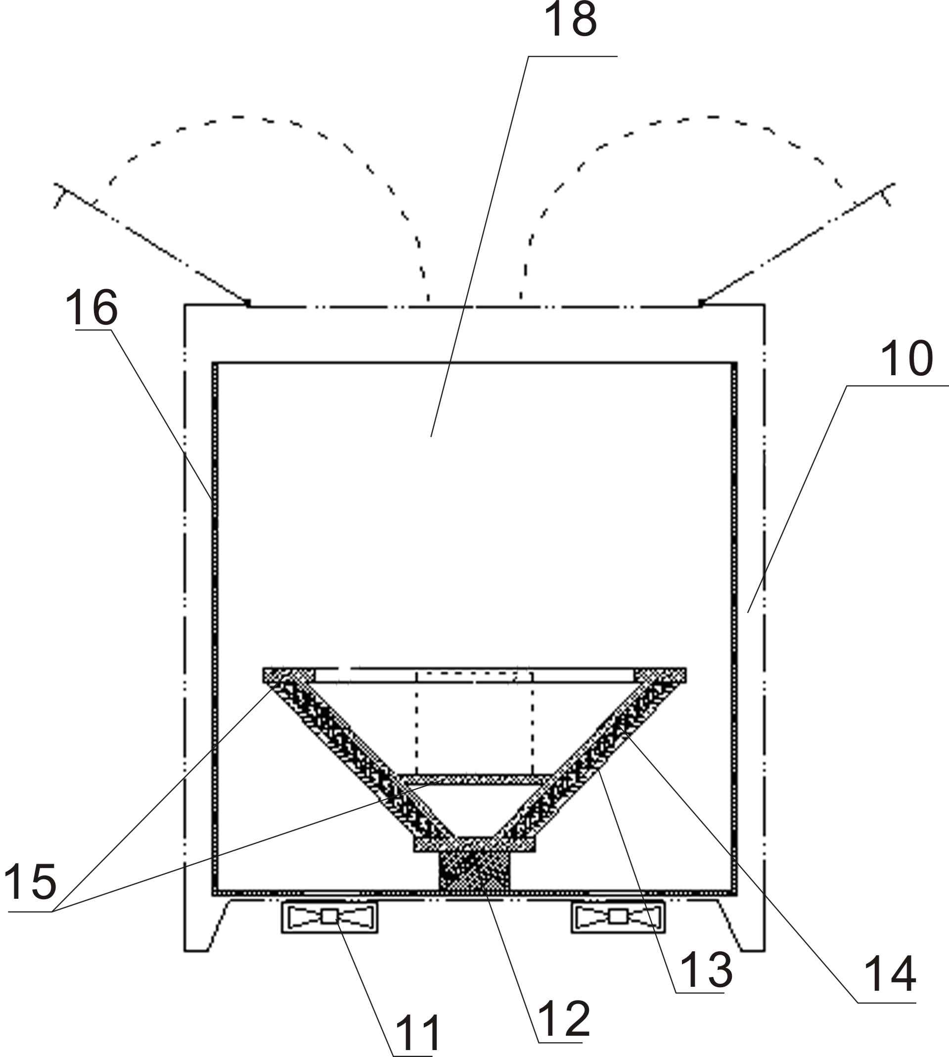
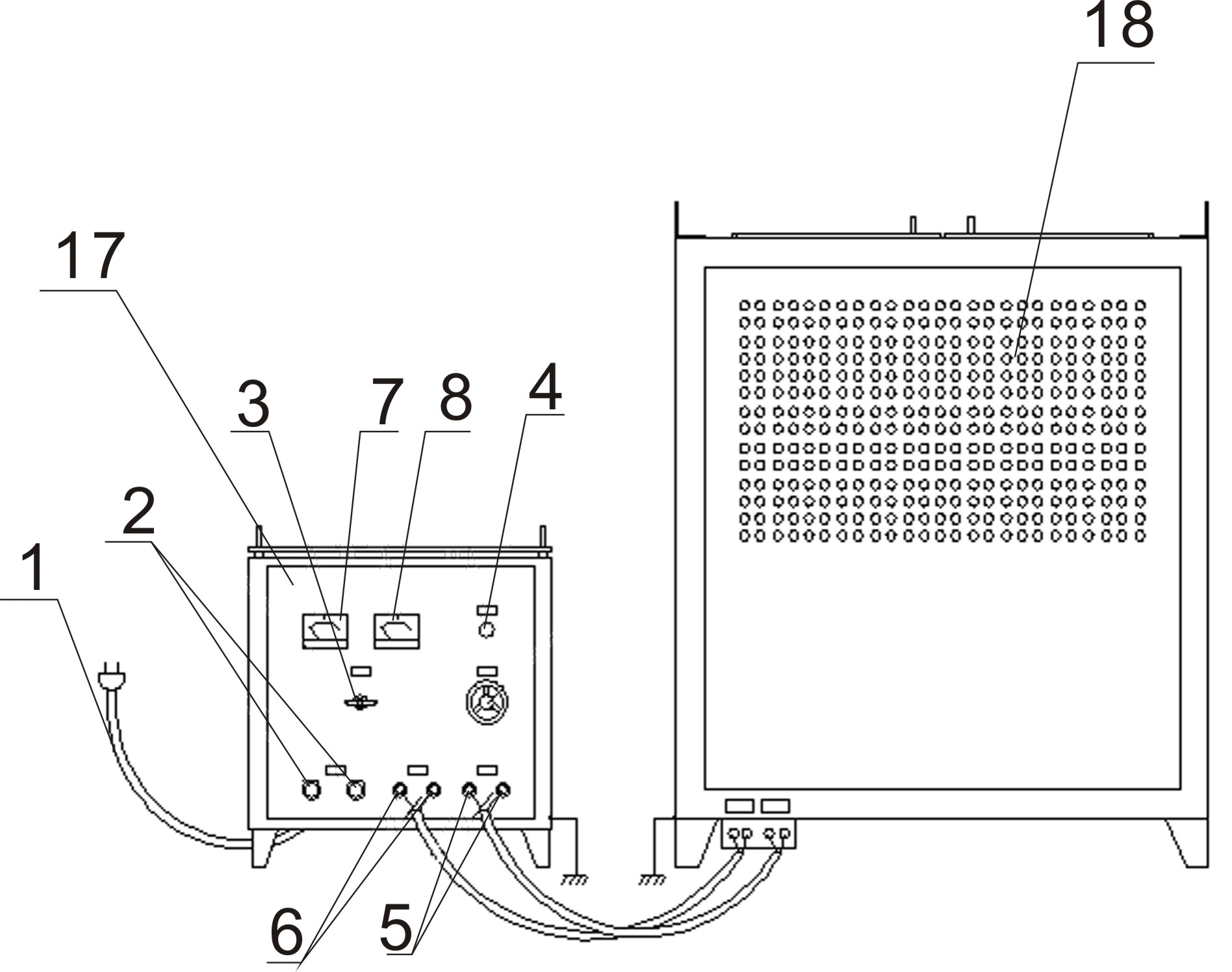
The invention relates to a magnetic field testing device and method. The testing device provided by the invention comprises a control power supply and a host which is connected with the control power supply, wherein the host comprises a cabinet; the inner wall of the cabinet is provided with a shielding layer; a support is arranged on the base of the cabinet; the support is connected with a framework; a coil winding is arranged on the framework; the outer side of the framework is provided with an insulating layer; and a cooling fan is arranged below the base of the cabinet. In the invention, the simulation of the actual physical and mechanical properties of geomechanics is realized based on the principles of simulating gravity by utilizing an electromagnetic force and simulating a gravityfield by utilizing an electromagnetic force field. A powdery magnetic material is blended into rock soil so that the magnetic force action on the rock soil in the magnetic field is overlapped on the original gravity, thereby achieving the effect of simulating the ng gravity field, improving the stress level of a model test material, and providing basic equipment for the magnetic force model test of the geomechanics.

Application Domain

Technology Topic

Stress levelEngineering +8

Image

  • Geomechanical magnetic field testing device and method
  • Geomechanical magnetic field testing device and method
  • Geomechanical magnetic field testing device and method

Examples

  • Effect test(1)

Test Example

[0035] A geomechanical magnetic field test method, including the following steps:
[0036] 1). The power input port 1 of the control power supply 17 is connected to the 220V power supply, and the control power supply 17 is connected to the host 18;
[0037] 2) The gradient magnetic field test area is located in the middle of the coil winding 14 of the gradient magnetic field test device. The gradient magnetic field test device provides a magnetic field with a linear gradient in the vertical direction, and the other two directions on the horizontal plane are basically uniform.
[0038] 3) Put the test materials into the gradient magnetic field test area of ​​the host 18;
[0039] 4) Turn on the control power supply 17, and after the power indicator light 4 shows normal, the cooling fan 12 starts;
[0040] 5) Adjust the adjustment handle 19 to supply power to the coil winding 14, read the values ​​displayed by the ammeter 7 and the voltmeter 8 according to the test needs, adjust the current to the set value, and perform the test.
[0041] 6) After the test is completed, adjust the adjustment handle 19 to adjust the current to zero. After the cooling fan 12 cools the host 18, turn off the control power supply 17.
[0042] The control power supply 17 adopts an adjustable DC power supply in a power frequency full-wave rectification mode.
[0043] The coil winding 14 of the gradient magnetic field region is made of an axisymmetric coil by winding a wire with one turn next to one turn. The coil turns are uniformly wound in the radial and axial directions, and the current is evenly distributed along the cross section. The direction of density and the positive direction of the axis of symmetry form a right-handed spiral relationship.
[0044] The intensity of the magnetic field can be adjusted by changing the current intensity by adjusting the handle 9 as required by the test.
[0045] The gradient magnetic field test device uses the cold-rolled silicon steel strip shielding layer 16 and the iron cabinet 10 to magnetically shield and protect the test magnetic field.
[0046] The upper part of the cabinet body 10 is a double-opening cabinet door, and the cabinet door is closed during the test to form an external magnetic shield.
[0047] Such as figure 1 As shown, the present invention is composed of a control power supply 17 and a test host 18. The 17 parts of the control power supply mainly include: AC 220V power input: 1, fuse 2, power switch 3, power indicator 4, fan power output 5, magnetic field power output 6, ammeter 7, voltmeter 8, magnetic field strength Adjust handle 9. The test host 18 mainly includes a cabinet 10, a cooling fan 11, a nylon support 12, an insulating layer 13, a coil winding 14, a glass fiber reinforced plastic frame 15, and a shielding layer 16 formed by cold-rolled silicon steel plate.
[0048] Such as figure 2 As shown, the magnetic field production method of the gradient magnetic field test device of the present invention is a single-coil truncated cone type, with a lower base radius of 5 cm, an upper base radius of 35 cm, and a height of 30 cm. The coil winding 14 of the gradient magnetic field test device is made of an axisymmetric coil by winding a wire with one turn next to one turn. The coil turns are uniformly wound in the radial and axial directions, and the current is uniformly distributed along the cross section, and the current density The direction and the positive direction of the axis of symmetry form a right-handed spiral relationship. Both the coil bobbin and the test platform are made of FRP materials, which have sufficient mechanical strength. The gradient magnetic field test device adopts the adjustable DC power supply of the power frequency full wave rectification method. Because the test device requires the power supply to provide a higher DC working voltage and higher power, under normal conditions, the adjustable DC power supply using the power frequency full-wave rectification method, compared with the switching DC power supply, reduces electromagnetic pollution to the environment and works reliably. Sexually beneficial.
[0049] The gradient magnetic field generator is placed in the center of the bottom of the shield in the cabinet 10, and the gradient magnetic field test area is in the middle of the coil winding 14. The gradient magnetic field test device provides a linear gradient in the vertical direction, and the other two directions on the horizontal plane are basically uniform magnetic fields. The intensity of the magnetic field can be adjusted by adjusting the magnetic field intensity adjustment handle 9 to change the current intensity according to the test needs.
[0050] The gradient magnetic field test device uses forced air cooling to dissipate the temperature rise of the coil winding 14 caused by the heating effect of the current. The four cooling fans 11 at the bottom of the cabinet body 10 form a cooling air path through the sieve wind windows at the bottom of the shielding layer 16 and the sieve-shaped openings on the four sides of the cabinet body 10.
[0051] The gradient magnetic field test device takes a number of corresponding protective measures according to the possible influence of temperature rise on the coil insulation strength and electromagnetic force. The gradient magnetic field test device uses the cold-rolled silicon steel strip shielding layer 16 and the iron cabinet 10 to magnetically shield the test magnetic field. The upper part of the cabinet body 10 is a double-open cabinet door, and the cabinet door is closed during the test to form an external magnetic shield.
[0052] Implementation steps:
[0053] First connect the AC 220V power input port 1 of the control power supply 17 to the laboratory circuit to provide power for the entire device. Connect the output terminal 6 of the magnetic field power supply with the input terminal, the output terminal 5 of the fan power supply and the input terminal with wires respectively to provide power for the coil winding 14 of the test host 18 and the cooling fan 11, put the test materials into the gradient magnetic field test area, and turn on the power After the power indicator 4 shows normal, the cooling fan 11 is started, the magnetic field intensity adjustment handle 9 supplies power to the coil winding 14, and the strength of the generated magnetic field is changed by adjusting the current input to the coil winding 14 of the test host 18, According to the needs of the test, read the values ​​displayed by the ammeter 7 and the voltmeter 8. After adjusting the current to the set value, perform the test. After the test is completed, adjust the magnetic field intensity adjustment handle 9 to adjust the current to zero. After the cooling fan 11 cools the coil winding 14 of the test host 18, turn off the power switch.

PUM

no PUM

Description & Claims & Application Information

We can also present the details of the Description, Claims and Application information to help users get a comprehensive understanding of the technical details of the patent, such as background art, summary of invention, brief description of drawings, description of embodiments, and other original content. On the other hand, users can also determine the specific scope of protection of the technology through the list of claims; as well as understand the changes in the life cycle of the technology with the presentation of the patent timeline. Login to view more.

Similar technology patents

Nano talcpowder modified polypropylene composite material and preparation method thereof

ActiveCN102532685AHigh rigidity and toughnessWide range of applicationsMicron scalePolypropylene composites
Owner:SHANGHAI PRET COMPOSITES

Classification and recommendation of technical efficacy words

  • Wide range of applications
  • Good uniformity

Method for preparing Nano silver grain, and prepared Nano silver grain

InactiveCN101050315ASmall average particle sizeGood uniformityBiocideCatalyst carriersAg nanoparticlesNanometre
Owner:SHANGHAI INST OF APPLIED PHYSICS - CHINESE ACAD OF SCI
Why Eureka
Try Eureka