
Semiconductor device and manufacturing method thereof

A manufacturing method and semiconductor technology, applied in the direction of semiconductor devices, radiation control devices, electric solid devices, etc., to achieve the effect of eliminating electrical crosstalk

Active Publication Date: 2011-10-12
TAIWAN SEMICON MFG CO LTD
View PDF3 Cites 5 Cited by
  • Summary
  • Abstract
  • Description
  • Claims
  • Application Information

AI Technical Summary

Problems solved by technology

However, the light directed toward one sensing pixel also has part of the light directed toward other sensing pixels, which causes optical and electrical crosstalk between different sensing pixels, and has not yet been resolved

Method used


Image

  • Semiconductor device and manufacturing method thereof
  • Semiconductor device and manufacturing method thereof
  • Semiconductor device and manufacturing method thereof

Examples


Embodiment Construction

[0037] Hereinafter, each embodiment is described in detail and examples accompanied by accompanying drawings are used as a reference basis of the present invention. In the drawings or descriptions in the specification, the same reference numerals are used for similar or identical parts. And in the drawings, the shapes or thicknesses of the embodiments may be enlarged, and marked for simplicity or convenience. Furthermore, parts of each element in the drawings will be described separately, and it should be noted that elements not shown or described in the drawings are forms known to those skilled in the art.

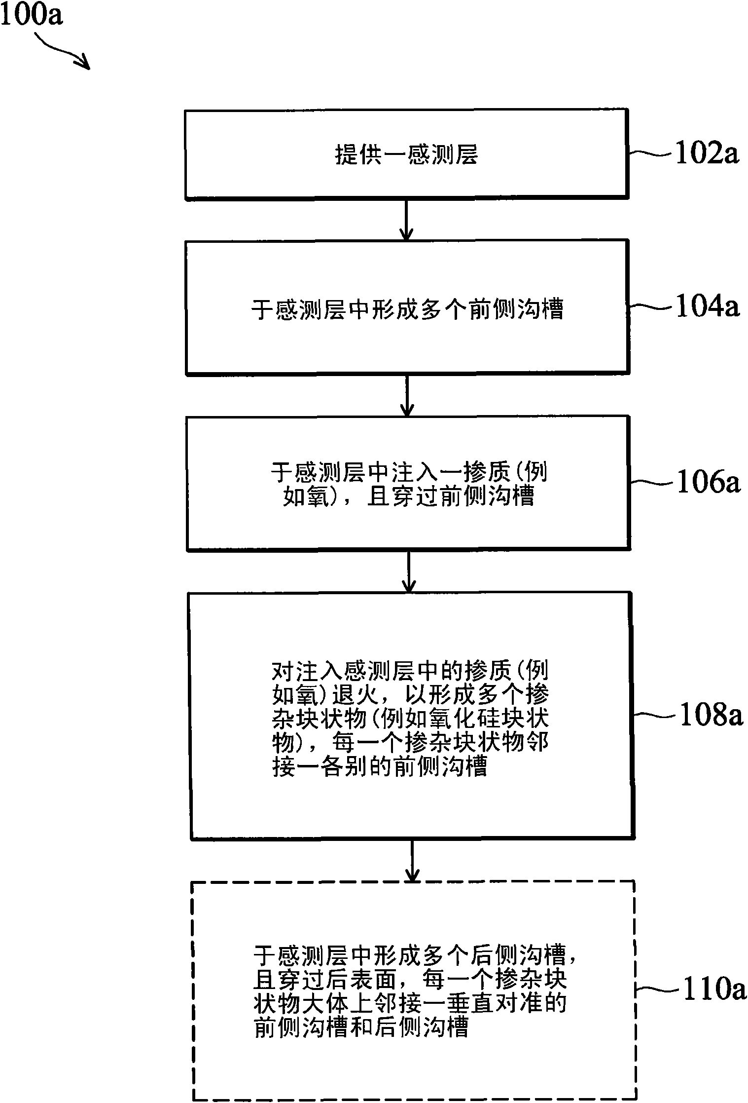
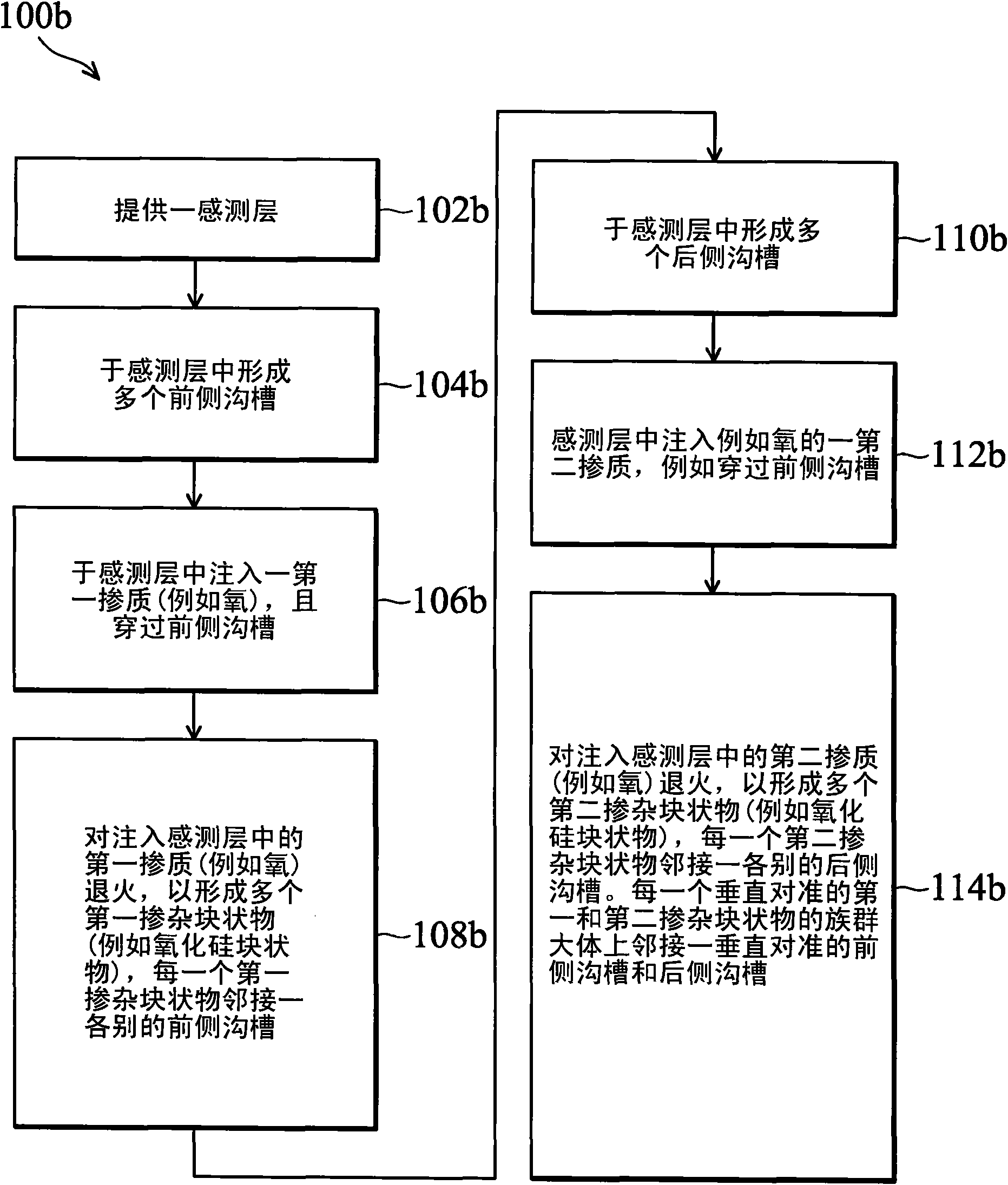
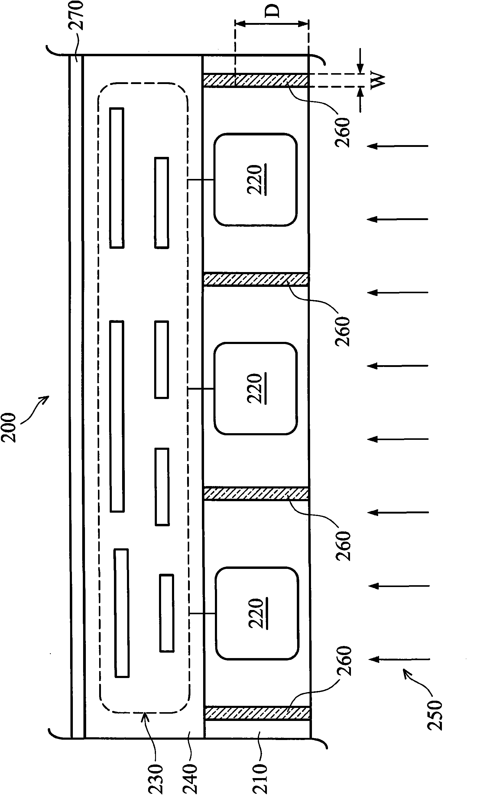
[0038] Please refer to the attached picture, Figure 1A and Figure 1B It is a flow chart of a method for manufacturing a semiconductor device including an isolation structure according to different embodiments of the present invention. Figure 2A and Figure 2B A schematic partial cross-sectional view and a plan view of a semiconductor device including a sensor isolat...


PUM


Abstract

The present disclosure provides methods and apparatus for sensor element isolation in a backside illuminated image sensor. In one embodiment, a method of fabricating a semiconductor device includes providing a sensor layer having a frontside surface and a backside surface, forming a plurality of frontside trenches in the frontside surface of the sensor layer, and implanting oxygen into the sensor layer through the plurality of frontside trenches. The method further includes annealing the implanted oxygen to form a plurality of first silicon oxide blocks in the sensor layer, wherein each first silicon oxide block is disposed substantially adjacent a respective frontside trench to form an isolation feature. The invention could prevent the photoelectron from leaking to the adjacent pixel so as to reduce or substantially eliminate the electric cross talk between the sensor elements.

Description

technical field [0001] The invention relates to a semiconductor device and a manufacturing method thereof, in particular to a method and device for isolating a sensing element of a back-illuminated sensor. Background technique [0002] In semiconductor processing, backside illuminated sensors are used to sense the amount of exposed light projected onto the rear surface of a substrate or sensing layer. Back-illuminated sensors may be formed in a substrate, and light is projected onto the rear surface of the substrate to reach the sensor. However, the light directed toward one sensing pixel also has part of the light directed toward other sensing pixels, which causes optical and electrical crosstalk between different sensing pixels, and has not yet been solved. [0003] Therefore, in this technical field, there is a need for a semiconductor device and its manufacturing method to meet the above-mentioned needs and overcome the shortcomings of the prior art. In particular, the...

Claims


Application Information

Patent Timeline
Patent Type & Authority Applications(China)
IPC IPC(8): H01L27/146
CPCH01L27/14621H01L27/14627H01L27/1463H01L27/1464H01L27/14689
Inventor 萧茹雄蔡昆佑曾建贤伍寿国郑乃文
Owner TAIWAN SEMICON MFG CO LTD
Learn More