A flexible e-fluidic packaging method that improves ductility

An encapsulation method and ductility technology, applied in decorative arts, microstructure devices, processing microstructure devices, etc., can solve the problem of difficult to ensure the deformation mode of the interconnect structure, affect the tensile properties of the interconnect structure, and the tensile ability of the interconnect structure. Binding and other problems to achieve the effect of improving work stability, good support, and avoiding electrical breakdown

Active Publication Date: 2016-01-13
HUAZHONG UNIV OF SCI & TECH
View PDF5 Cites 0 Cited by
  • Summary
  • Abstract
  • Description
  • Claims
  • Application Information

AI Technical Summary

Problems solved by technology

The problem with this method is that the incompatibility of the flexible interconnect structure with the adhesive layer and the substrate will affect the tensile properties of the interconnect structure, and during the stretching process, the stretchability of the interconnect structure is affected by the adhesive. Adhesive layer and substrate bound and not fully applied
[0004] However, further studies have shown that the above existing technologies still have the following problems: 1) the interconnection structure used is prone to out-of-plane buckling, and it is difficult to guarantee the deformation mode of the interconnection structure during stretching; 2) lack of In-depth research on the relationship between the suspension medium and the packaging structure, the performance of the final packaging structure still needs to be improved; 3) The interconnection structure and the triangular-conical boss structure used need to be made by photolithography and other processes. complicated and costly

Method used


Image

  • A flexible e-fluidic packaging method that improves ductility
  • A flexible e-fluidic packaging method that improves ductility
  • A flexible e-fluidic packaging method that improves ductility

Examples


Embodiment Construction

[0028] In order to make the objectives, technical solutions and advantages of the present invention clearer, the following further describes the present invention in detail with reference to the accompanying drawings and embodiments. It should be understood that the specific embodiments described herein are only used to explain the present invention, but not to limit the present invention. In addition, the technical features involved in the various embodiments of the present invention described below can be combined with each other as long as they do not conflict with each other.

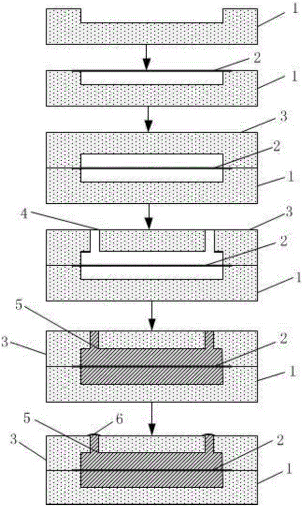
[0029] figure 1 It is used to show the flow diagram of the fluid encapsulation process of the present invention. Refer to below figure 1 To explain the specific operation process in detail.

[0030] First, according to the structure of the microcavity, a mold with the corresponding structure can be designed and prepared, such as figure 1 As shown in the figure, the Ecoflex solution is configured, and th...


PUM

PropertyMeasurementUnit
electrical resistivityaaaaaaaaaa
dielectric strengthaaaaaaaaaa
viscosityaaaaaaaaaa

Abstract

The invention discloses a flexible electronic fluid encapsulation method capable of improving ductility. The flexible electronic fluid encapsulation method comprises the following steps: preparing an upper encapsulation structure and a lower encapsulation structure, wherein the two encapsulation structures are symmetrical and areas concavely extending are formed in central parts of the encapsulation structures; manufacturing a ductility interconnection structure which is of a curve structure with overall wavy distribution; correspondingly laminating the upper encapsulation structure and the lower encapsulation structure, and encapsulating the ductility interconnection structure in a hollow micro cavity; and finally, injecting insulation fluid into the micro cavity so that the micro cavity is filled with the insulation fluid and the ductility interconnection structure is coated, and therefore, the overall fluid encapsulation operation is completed. By virtue of the flexible electronic fluid encapsulation method capable of improving ductility, the tensile property of the interconnection structure can be remarkably improved; the phenomenon that the surface warps outwards is avoided; the quality can be controlled; meanwhile, the stability of the interconnection structure can be effectively improved.

Description

Technical field [0001] The invention belongs to the technical field of flexible electronics manufacturing, and more specifically, relates to a flexible electronic fluid packaging method capable of improving ductility. Background technique [0002] Flexible electronics is an emerging electronic technology that manufactures electronic devices on flexible or malleable plastic or thin metal substrates. Because of its unique flexibility, ductility, and high-efficiency and low-cost manufacturing characteristics, it is used in information, energy, medical , National defense and other fields have broad application prospects. At present, for the flexible electronic interconnection structure, the main manufacturing process used is to directly print the flexible interconnection structure on the elastic substrate by a printing method, and fix it with the elastic substrate through an adhesive layer. The problem with this method is that the incompatibility of the flexible interconnect structu...

Claims


Application Information

Patent Timeline
Patent Type & Authority Patents(China)
IPC IPC(8): B81C3/00B81C1/00
Inventor 黄永安王曳舟董文涛黄涛
Owner HUAZHONG UNIV OF SCI & TECH
Why Eureka
Try Eureka