Substrate processing apparatus

A substrate processing device and processing device technology, applied in transportation and packaging, rain/wind shields, building components, etc., can solve the problem of increasing the amount of liquid medicine or pure water used, the complexity of the composition or control mechanism, and the cost of device manufacturing Improvement and other issues, to achieve the effect of saving space, miniaturizing the device, and reducing the amount of use

Inactive Publication Date: 2005-07-13
DAINIPPON SCREEN MTG CO LTD
View PDF1 Cites 18 Cited by
  • Summary
  • Abstract
  • Description
  • Claims
  • Application Information

AI Technical Summary

Problems solved by technology

For example, in an etching treatment device, an etching treatment chamber, a water washing treatment chamber, and a drying treatment chamber must be continuously installed along the conveying direction of the substrate. The overall size of the device increases, and the space occupied in the cleaning room is large, and the manufacturing cost of the device is also increased. up
In addition, due to the large processing chamber, the amount of chemical solution or pure water used will also increase
[0005] On the other hand, a substrate processing apparatus that does not provide a processing chamber but is equipped with a processing apparatus smaller than a substrate is advantageous in terms of installation space and manufacturing cost, and can also reduce the amount of chemical liquid or pure water used. However, it is necessary to prevent chemical liquid or pure water from The means or control of the outflow or scattering of water to the outside of the discharge passage complicates the composition or control mechanism of the device
Spray or evaporated gas of the treatment liquid may spread from the opening of the nozzle structure to the surrounding environment

Method used


Image

  • Substrate processing apparatus
  • Substrate processing apparatus
  • Substrate processing apparatus

Examples


Embodiment Construction

[0031] refer to Figure 1 ~ Figure 1 1 illustrates a preferred embodiment for carrying out the invention.

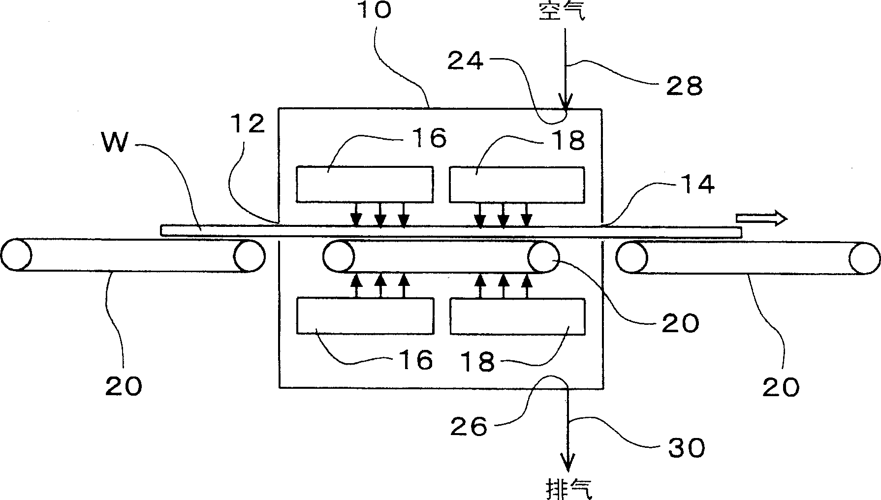
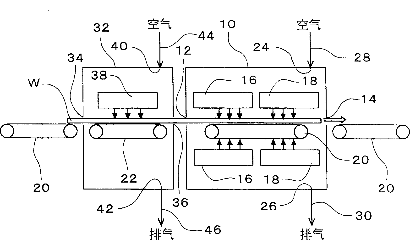
[0032] figure 1 It is a schematic diagram showing an example of an embodiment of the present invention and a schematic configuration of a substrate processing apparatus.

[0033] This substrate processing apparatus is provided with the airtight processing chamber 10 that has substrate carrying inlet 12 and substrate carrying outlet 14, is equipped with ultrasonic wave · high-pressure jet cleaning · water washing processing part 16 and air knife drying processing part 18 in processing chamber 10, as The substrate W is a processing apparatus for performing predetermined processing. The ultrasonic, high-pressure jet cleaning, and water washing processing unit 16 and the air knife drying processing unit 18 are arranged on the upper side and the lower side of the transport path of the substrate W, respectively. In addition, a roller conveyor 20 is also provided for transpo...


PUM


Abstract

PROBLEM TO BE SOLVED: To provide equipment wherein the equipment can be miniaturized, while the configuration equipped with a chamber in which treatment tools are arranged in the inside, and consumption of treatment liquid can be also reduced. SOLUTION: The chamber 10 of a tightly closed type, which has a substrate carry-in port 12 and a substrate taking out port 14, the processing tools 16, 18 arranged inside the chamber, and a roller transfer 20 which transfers a substrate W are installed. The length of the chamber is made smaller than the dimensions in the substrate transfer direction. An air supply pipe 28 for supplying air for purging into the chamber, and an exhaust pipe 30 for exhausting air for purging, from the inside of the chamber are installed, and internal atmosphere and external atmosphere of the chamber are isolated from each other. COPYRIGHT: (C)2005,JPO&NCIPI

Description

technical field [0001] The present invention relates to a method for carrying out substrates such as semiconductor wafers, glass substrates for flat panel displays (FPD), glass substrates for photomasks, printed circuit boards, etc., for ultrasonic and high-pressure spray cleaning, water washing, and air knife drying. Substrate processing equipment for various processing such as processing, etching processing, developing processing, and peeling processing. Background technique [0002] When performing wet processing such as ultrasonic and high-pressure jet cleaning treatment, water washing treatment, and etching treatment on substrates such as semiconductor wafers and FPD glass substrates, a substrate processing device with a processing chamber equipped with ultrasonic and high-pressure equipment is used. Processing equipment such as spray cleaning equipment, water washing equipment, etching equipment, etc. Accordingly, while the substrate is being conveyed by a conveying m...

Claims


Application Information

Patent Timeline
Patent Type & Authority Applications(China)
IPC IPC(8): B65G49/00B08B3/00B08B5/00B65G49/06B65G49/07C23G3/00H01L21/00H01L21/02H01L21/027H01L21/302H01L21/304H01L21/306H01L21/677H01L21/68
CPCE05Y2800/422E05Y2800/428E06B1/62E06B7/26E06B2001/622E06B2001/628
Inventor 山本悟史志摩康正
Owner DAINIPPON SCREEN MTG CO LTD
Why Eureka
Try Eureka