Gas laser device

一种气体激光、排气装置的技术,应用在激光器、激光器零部件、电气元件等方向,能够解决激光加工作业效率恶化、花费时间等问题

Active Publication Date: 2011-10-12
FANUC LTD
View PDF4 Cites 18 Cited by
  • Summary
  • Abstract
  • Description
  • Claims
  • Application Information

AI Technical Summary

Problems solved by technology

Therefore, it takes time to return to the state where laser oscillation can be performed, which causes deterioration of work efficiency such as laser processing.

Method used


Image

  • Gas laser device
  • Gas laser device
  • Gas laser device

Examples


Embodiment Construction

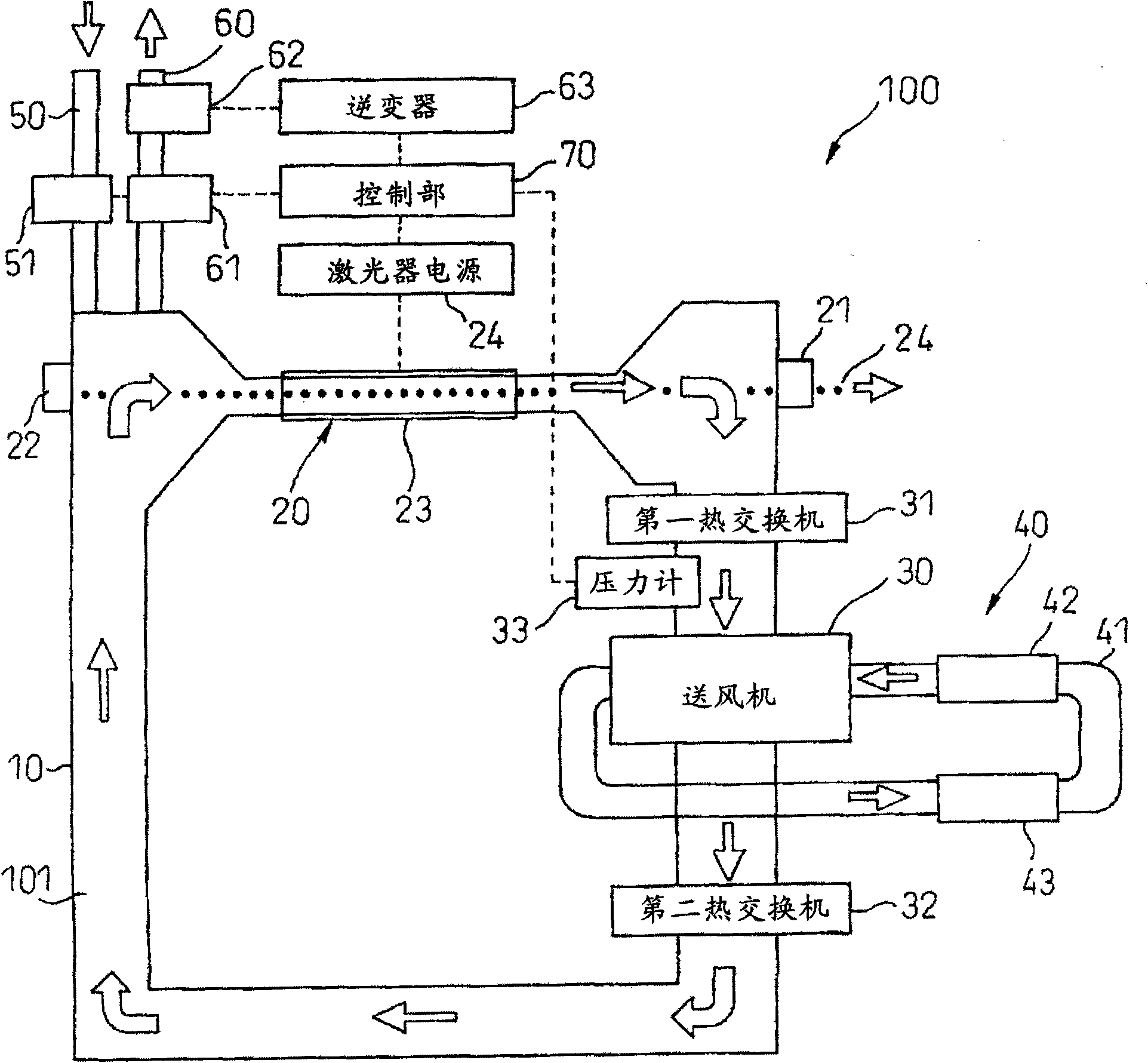
[0014] Refer below Figure 1 ~ Figure 6B Embodiments of the present invention will be described. figure 1 It is a figure which schematically shows the structure of the gas laser apparatus 100 which concerns on embodiment of this invention. This gas laser device 100 has a laser gas container 10 forming a gas flow path 101 through which laser gas circulates, and a laser oscillator 20 and a blower 30 arranged on the gas flow path 101 . The gas laser device 100 of this embodiment can be used in a wide range of fields such as processing, medical treatment, and measurement.

[0015] The laser gas container 10 seals a predetermined laser gas in a state isolated from the atmosphere. As the laser gas, a medium gas for laser oscillation containing a laser medium such as carbon dioxide gas, nitrogen gas, or argon gas can be used.

[0016] The laser oscillator 20 has an output mirror 21 , a back mirror 22 , and a discharge tube 23 arranged between the output mirror 21 and the back mirr...


PUM


Abstract

A gas laser device including a blower circulating a laser gas along a gas passage; a pressure detection section detecting a gas pressure of the laser gas in the gas passage; a gas supply and exhaust section supplying the laser gas to the gas passage and exhausting the laser gas from the gas passage; an instruction section instructing a temporary stop of a laser oscillation by a laser oscillator; and a control section controlling the blower and the gas supply and exhaust section in response to an instruction from the instruction section. The control section, before the instruction section instructs the temporary stop, controls the blower to rotate at a predetermined rotation number and controls the gas supply and exhaust section so that the gas pressure detected by the pressure detection section is a first target gas pressure and, once the instruction section instructs the temporary stop, controls the blower so as to reduce the rotation number of the blower or stop the rotation of the blower and controls the gas supply and exhaust section so that the gas pressure detected by the pressure detection section is a second target gas pressure corresponding to the first target gas pressure during the rotation of the blower.

Description

technical field [0001] The present invention relates to a gas laser device using gas as an excitation medium. Background technique [0002] There is known a gas laser device that encloses laser gas as an excitation medium in a laser gas container, circulates the laser gas with a blower, and excites the laser gas by discharge from a discharge electrode to emit laser light. In the device described in Japanese Patent Application Laid-Open No. 11-112064 (JP11-112064A), the blower is rotated when the laser output laser is on, and the blower is temporarily stopped when the laser is not on. [0003] However, as in the device described in JP11-112064A, when the blower is temporarily stopped when the laser is not turned on, the gas pressure in the container may change due to leakage of the laser gas container. In addition, when the temporary stop is released in this state and the blower is rotated again, it is necessary to fill or discharge the laser gas into the container and adjus...

Claims


Application Information

Patent Timeline
Patent Type & Authority Applications(China)
IPC IPC(8): H01S3/036H01S3/041
CPCH01S3/036H01S3/09702H01S3/104
Inventor 村上孝文西尾明彦
Owner FANUC LTD
Why Eureka
Try Eureka