
Signal transmitting circuit and signal transmitting method

A signal transmission and signal generation circuit technology, applied in transmission systems, digital transmission systems, electrical components, etc., can solve problems such as power consumption, reduced power efficiency of transmitters, and power wasted transmitter characteristic impedance, and achieve high power efficiency. Effect

Active Publication Date: 2011-10-12
MEDIATEK INC
View PDF4 Cites 0 Cited by
  • Summary
  • Abstract
  • Description
  • Claims
  • Application Information

AI Technical Summary

Problems solved by technology

However, if this is done, the characteristic impedance of the transmitter will dissipate the same amount of power as the characteristic impedance of the loading device
therefore, the power efficiency of the transmitter is reduced because some of the power generated by the transmitter is not delivered to the loading device
More seriously, when more power is delivered to the loading device, more power is wasted on the characteristic impedance of the transmitter

Method used


Image

  • Signal transmitting circuit and signal transmitting method
  • Signal transmitting circuit and signal transmitting method
  • Signal transmitting circuit and signal transmitting method

Examples


Embodiment Construction

[0012] Certain terms are used throughout the specification and preceding claims to refer to particular components. Those of ordinary skill in the art should understand that hardware manufacturers may use different terms to refer to the same component. This specification and the preceding claims do not use the difference in name as a way to distinguish components, but use the difference in function of components as a criterion for distinguishing. The "comprising" mentioned throughout the specification and the preceding claims is an open term, so it should be interpreted as "including but not limited to". In addition, the term "coupled" herein includes any direct and indirect means of electrical connection. Therefore, if it is described that a first device is coupled to a second device, it means that the first device may be directly electrically connected to the second device, or indirectly electrically connected to the second device through other devices or connection means. ...


PUM


Abstract

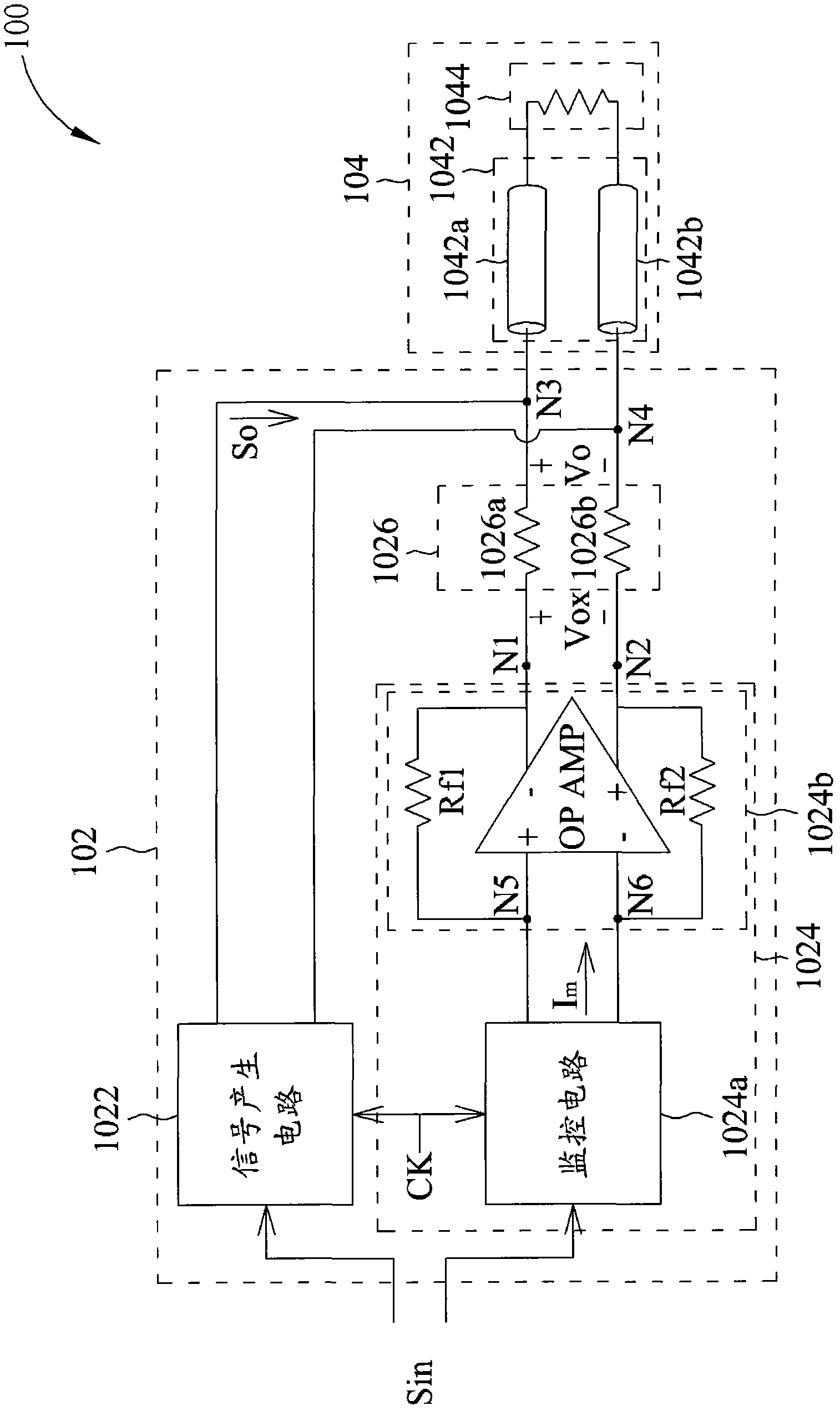
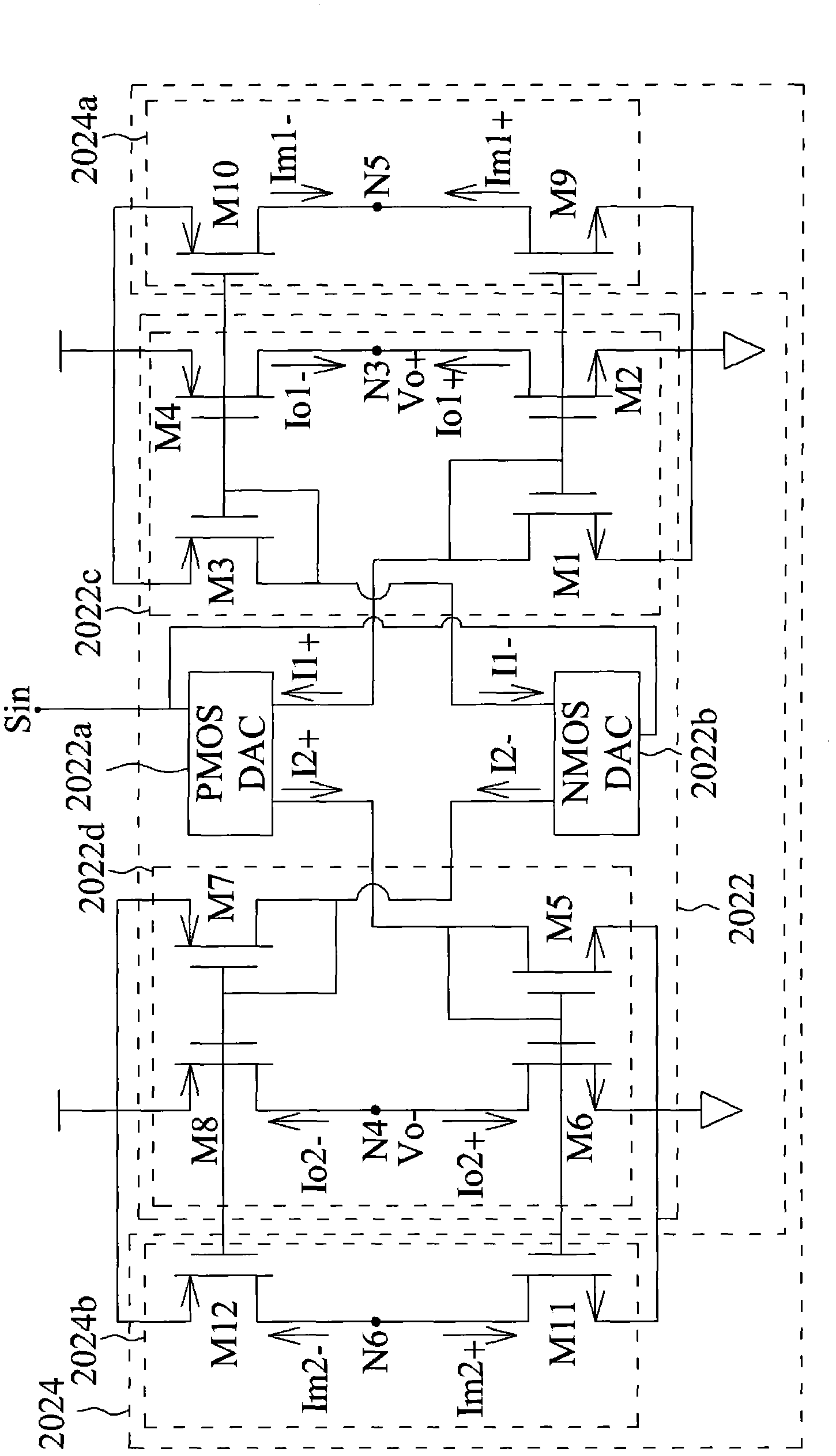
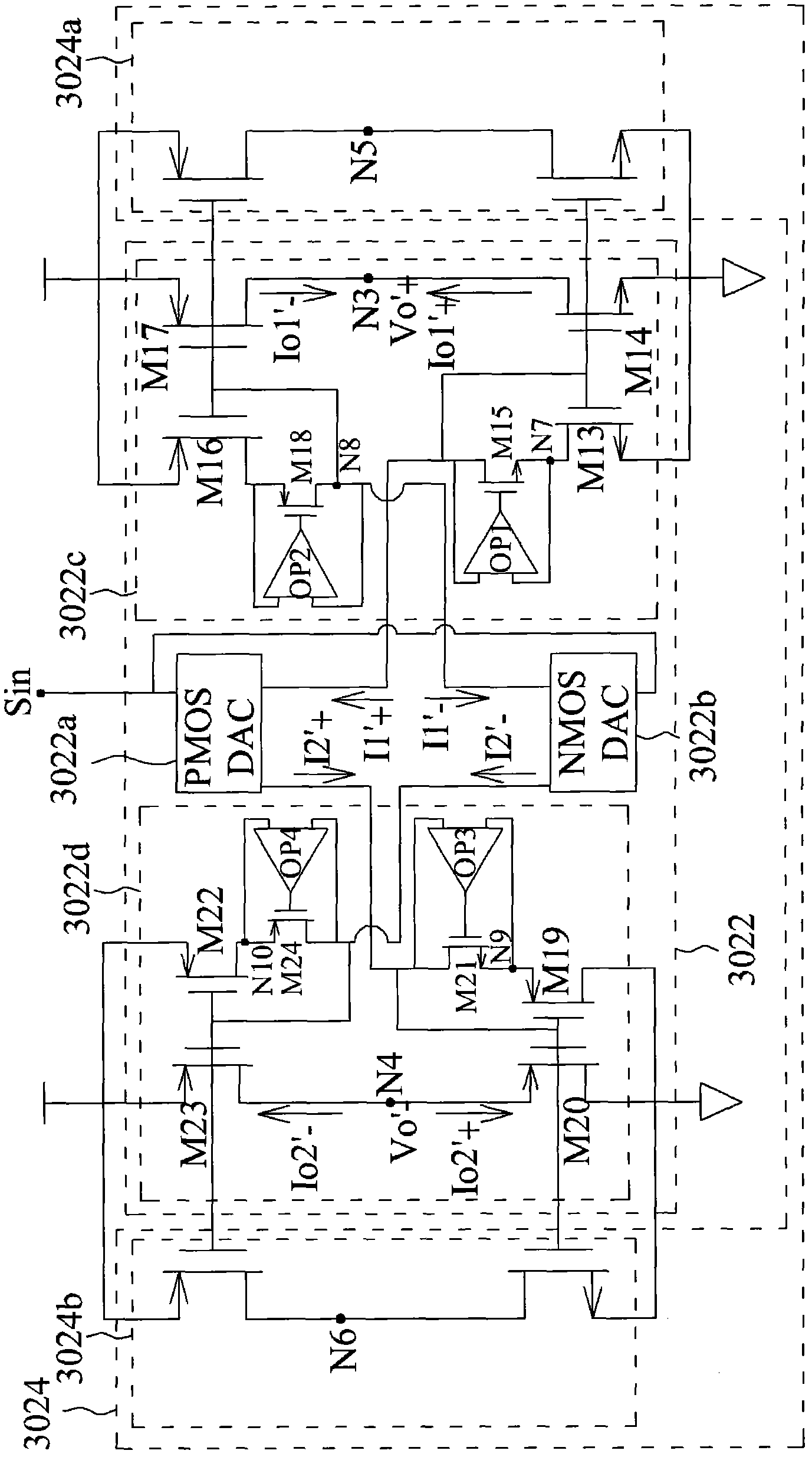
The invention provides a signal transmitting circuit and a signal transmitting method. The signal transmitting circuit includes: a signal generating circuit arranged to generate an output signal to a loading device according to an input signal; an adjusting circuit; and a matching circuit having a first port coupled to the adjusting circuit and a second port coupled to the signal generating circuit, wherein the second port is arranged to couple to the loading device so as to provide a matching impedance corresponding to the loading device; and the adjusting circuit is arranged to generate an adjusting signal of which a voltage applied on the first port is substantially equal to a voltage of the output signal applied on the second port. The provided signal transmitting circuit and the signal transmitting method has a power efficiency higher than the conventional technology.

Description

technical field [0001] The invention relates to a signal transmission circuit and a signal transmission method. Background technique [0002] In a communication system, such as a fiber optic communication system, a transmitter is used to send a data signal to a transmission medium, such as an optical fiber, which is responsible for delivering the data signal to a receiver. To maximize the transmitted power to the loading device (ie, transmission medium and receiver), the characteristic impedance of the transmitter (ie, the source impedance) should match that of the loading device (ie, the load impedance). In other words, the characteristic impedance of the transmitter should be equal to that of the loading device. However, if this is done, the characteristic impedance of the transmitter will dissipate the same amount of power as the characteristic impedance of the loading device. Therefore, the power efficiency of the transmitter is reduced because part of the power genera...

Claims


Application Information

Patent Timeline
IPC IPC(8): H04L25/02
CPCH04L25/0278
Inventor 张文华
Owner MEDIATEK INC
Learn More