Acceleration cavity and accelerator

A technology for accelerating chambers and shells, applied in the field of accelerating chambers and accelerators, can solve the problems of not being able to improve the Q value, and achieve the effect of improving the Q value and improving power efficiency

Active Publication Date: 2018-08-21
MITSUBISHI HEAVY IND MACHINERY SYST LTD +1
View PDF9 Cites 0 Cited by
  • Summary
  • Abstract
  • Description
  • Claims
  • Application Information

AI Technical Summary

Problems solved by technology

Therefore, conventional metal acceleration chambers have the problem of not being able to significantly increase the Q value compared to conventional ones due to the limitation of the physical property value inherent in metals called electrical conductivity.

Method used


Image

  • Acceleration cavity and accelerator
  • Acceleration cavity and accelerator
  • Acceleration cavity and accelerator

Examples


no. 1 Embodiment approach

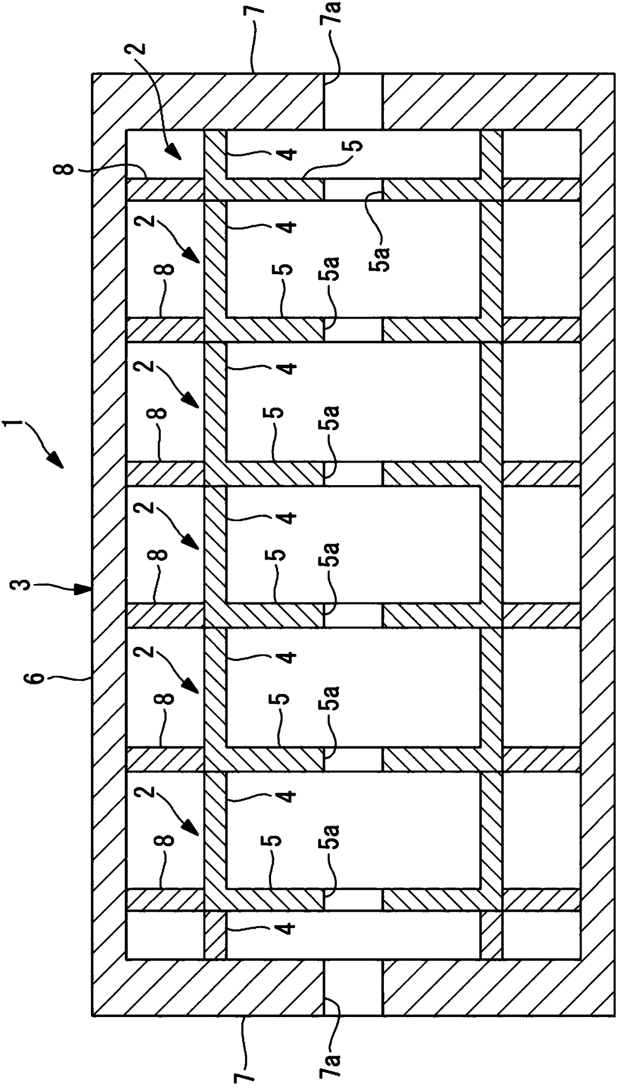
[0037] Below, use figure 1 The accelerator according to the first embodiment of the present invention will be described. figure 1 It is a longitudinal sectional view showing the high-frequency acceleration cavity according to the first embodiment of the present invention.

[0038] The accelerator involved in this embodiment has a high-frequency acceleration chamber 1, and the high-frequency acceleration chamber 1 will be referred to as TM 0n The higher-order mode of the mode (n>1) is used as the acceleration mode.

[0039] The high-frequency acceleration chamber 1 includes a plurality of acceleration units 2 including a dielectric, a cylindrical case 3 in which the plurality of acceleration units 2 are arranged, and the like. For the high-frequency acceleration cavity 1, charged particles pass on the central axis.

[0040] A plurality of acceleration units 2 are arranged in series in the beam axis direction from one end plate 7 of the housing 3 to the other end plate 7 insi...

no. 2 Embodiment approach

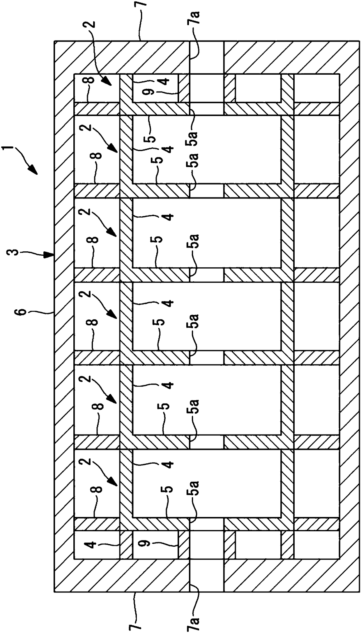
[0061] Next, use image 3 The radio-frequency acceleration chamber 1 according to the second embodiment of the present invention will be described. In the radio-frequency acceleration chamber 1 according to the present embodiment, the acceleration unit 2 adjacent to the end plate 7 of the case 3 among the acceleration units 2 is provided with a cylindrical portion 9 around the beam axis. In addition, the cylindrical portion 9 is provided on the acceleration unit 2 near the end plates 7 on both sides. The cylindrical portion 9 has the same inner diameter as the opening 5 a of the disk portion 5 , one end is connected to the end plate 7 of the case 3 , and the other end is connected to the disk portion 5 of the acceleration unit 2 .

[0062] The cylindrical portion 9 is the same dielectric material as the cylindrical portion 4 , the disc portion 5 , and the annular portion 8 described in the first embodiment.

[0063] In the first embodiment, the high-frequency magnetic field ...

no. 3 Embodiment approach

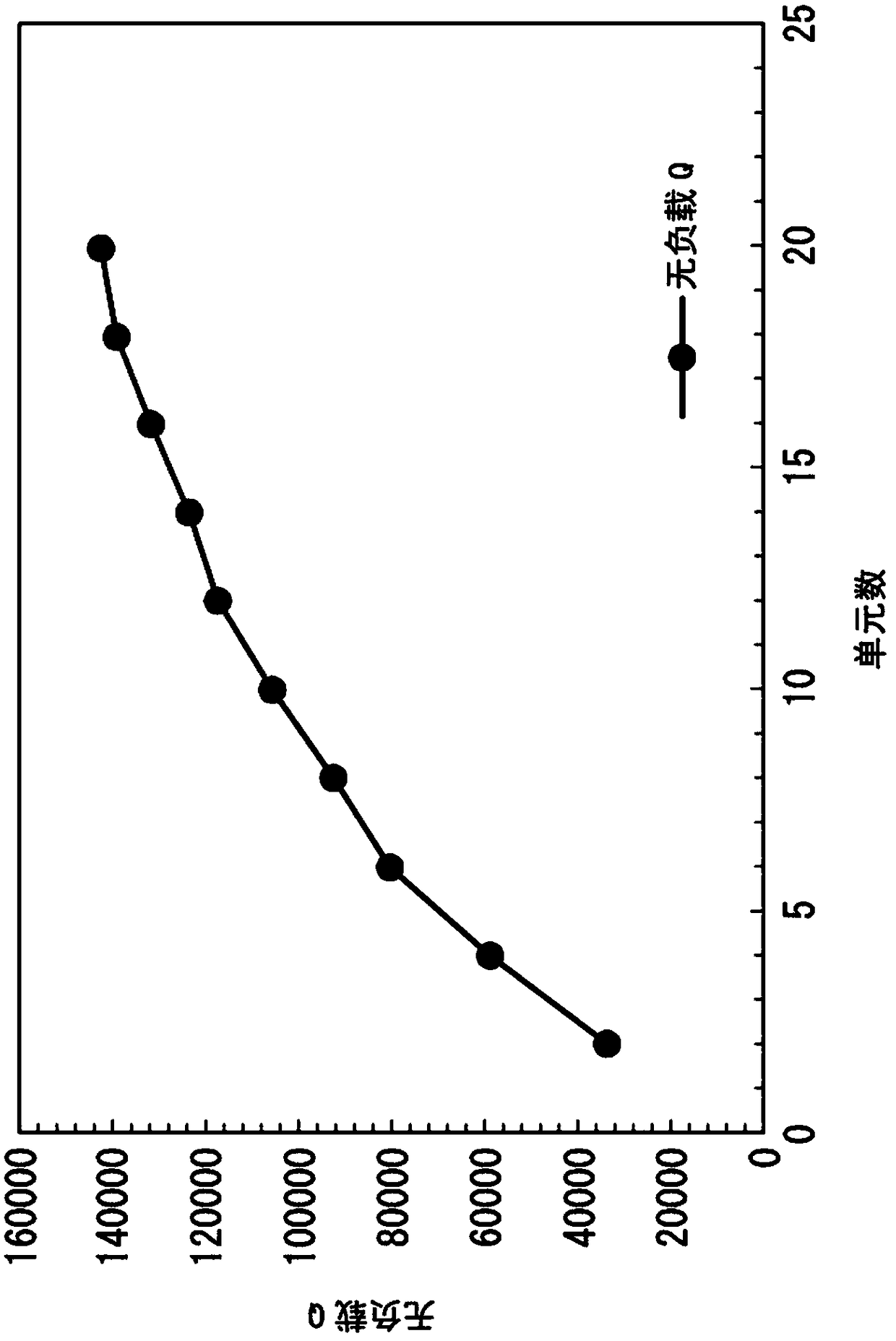
[0066] Next, use Figure 4 The radio-frequency acceleration chamber 1 according to the third embodiment of the present invention will be described. In the high-frequency acceleration chamber 1 according to the present embodiment, a plurality of cylindrical portions 4 with different diameters are concentrically arranged in one acceleration unit 2 . Accordingly, the high-frequency acceleration cavity 1 can use higher-order modes in the acceleration mode. In addition, as a result, the Q value can be further improved.

[0067] In the first embodiment, the case where only one cylindrical portion 4 is provided in each acceleration unit 2 has been described, but the present invention is not limited to this example. Two or more cylindrical parts 4 may be provided. exist Figure 4 In , an example in which two cylindrical parts 4 are provided is shown.

[0068] When two or more cylindrical parts 4 are provided, the central axes of the respective cylindrical parts 4 are arranged on ...


PUM


Abstract

The objective of the present invention is to provide an acceleration cavity and an accelerator such that the Q value can be increased compared to prior art normal conducting acceleration cavities, andpower efficiency can be increased. This high-frequency acceleration cavity (1) comprises: a housing (3) whereof the inner peripheral surface is cylindrical in shape, and electrically conductive at least on the surface thereof; and a plurality of acceleration cells (2) provided inside the housing (3), each being a dielectric having formed in a central portion thereof an opening (5a) wherethrough acharged particle can pass. The housing (3) has a cylinder body (6) having a cylindrical shape, and end plates (7) provided at both ends of the cylinder body (6). A plurality of the acceleration cells(2) are disposed throughout from the end plate (7) at one end side to the end plate (7) at the other end side of the housing (3). Each of the acceleration cells (2) comprises: a cylinder body (4) having a diameter smaller than the internal diameter of the cylinder body (6) from the housing (3); and a disc portion (5) where the opening (5a) is formed, fixed onto the cylinder body (4) on the innerside of the cylinder body (4), and disposed in such a manner that the plate surface thereof is orthogonal to the charged particle passage axis.

Description

technical field [0001] The invention relates to an acceleration cavity and an accelerator. Background technique [0002] The high-frequency acceleration cavity used in the accelerator for charged particle acceleration accumulates high-frequency power in the metal casing, and uses the high-frequency electric field generated therein to artificially accelerate charged particles such as electrons and ions to a high speed. Accelerators using high-frequency accelerating cavities are widely used in academic fields such as high-energy physics experiments and radiant light facilities, and in industrial fields such as radiation therapy / diagnostic equipment and sterilization equipment. [0003] High-frequency accelerating cavities are broadly classified into conventional accelerating cavities that use high-purity copper and operate at room temperature, and superconducting cavities that use superconducting materials (such as niobium) and operate at extremely low temperatures. [0004] ...

Claims


Application Information

Patent Timeline
IPC IPC(8): H05H7/18
CPCH05H7/22H05H9/02H05H7/18H05H9/005H05H9/00
Inventor 吉田光宏佐藤大辅重冈伸之三浦祯雄
Owner MITSUBISHI HEAVY IND MACHINERY SYST LTD
Why Eureka
Try Eureka