Clamp connector with improved structure for accumulator of car

A car battery and chuck technology, applied in structural parts, circuits, electrical components, etc., can solve the problems of difficult locking and matching construction, damaged threads of locking screws, discounts in electrical conductivity, etc. Efficiency, size and weight

Inactive Publication Date: 2004-12-29
梁世宗
View PDF0 Cites 0 Cited by
  • Summary
  • Abstract
  • Description
  • Claims
  • Application Information

AI Technical Summary

Problems solved by technology

[0003] However, the known structure uses the semicircular curved part of the elastic clip arm to tighten and fix the power connector of the battery. In order to make the elastic clip arm and the power connector of the battery tightly fit to improve the conductive effect, precise calculation and processing are required to improve the elasticity. The arc accuracy of the inner surface of the clamp arm can exert the close effect, otherwise it will produce such as figure 2 The contact gap A shown on the upper right greatly reduces the conductive performance; and the cost of precision machining is expensive, and it is not economical to use such a common and cheap product; and in order to ensure that the elastic clip arm only has long-lasting and appropriate elasticity, In order to improve the degree of fit, it is necessary to maintain a certain thickness of the elastic clip arm, and the thicker the thickness, the stronger the relative resistance tension. This will inevitably increase the force of the locking screw to make the two elastic clip arms Gradually bend inwards, which often causes difficulty in screwing and locking the locking screw; and if the screw is tightened hard, the elastic clamp arm will produce excessive resistance tension, which may cause the thread of the locking screw to be damaged; and because The locking screw is not easy to turn and lock, so there are often problems of inaccurate locking and loosening, which not only affects the conductive quality, but also often falls off and fails, which adds a lot of trouble;
[0004] If you want to connect a large number of wires, you need to increase the volume of the wiring part to process more locking holes to lock a considerable number of wires, which will increase the use of materials, and The cost is relatively increased, and the wiring part is provided with many locking holes of different sizes, and the distance between each locking hole is too small, which often results in difficulty in the locking construction; the disadvantages of the existing technology:
[0005] 1. In order to closely fit the elastic clamp arm and the power connector of the battery to improve the conductive performance, it is necessary to improve the bending accuracy of the inner surface of the elastic clamp arm through precise calculation and processing, which will increase the burden on production costs
[0006] 2. In order to ensure that the elastic clip arm has a long-lasting and appropriate elasticity to improve the degree of fit, it must maintain a certain thickness, which will inevitably increase the difficulty of screwing the locking screw due to the increase in the resistance tension.
[0007] 3. The locking screw is not easy to turn and lock, so the problem of loosening often occurs due to inaccurate locking, which in turn affects its conductive quality
[0008] 4. If the screw is tightened hard, the elastic clamp arm will produce excessive resistance tension, which may damage the screw that tightens the screw.
[0009] 5. High manufacturing cost
[0010] 6. Not progressive
[0011] 7. Lack of industrial competitiveness
[0012] 8. The volume and weight are relatively heavy

Method used


Image

  • Clamp connector with improved structure for accumulator of car
  • Clamp connector with improved structure for accumulator of car
  • Clamp connector with improved structure for accumulator of car

Examples


Embodiment Construction

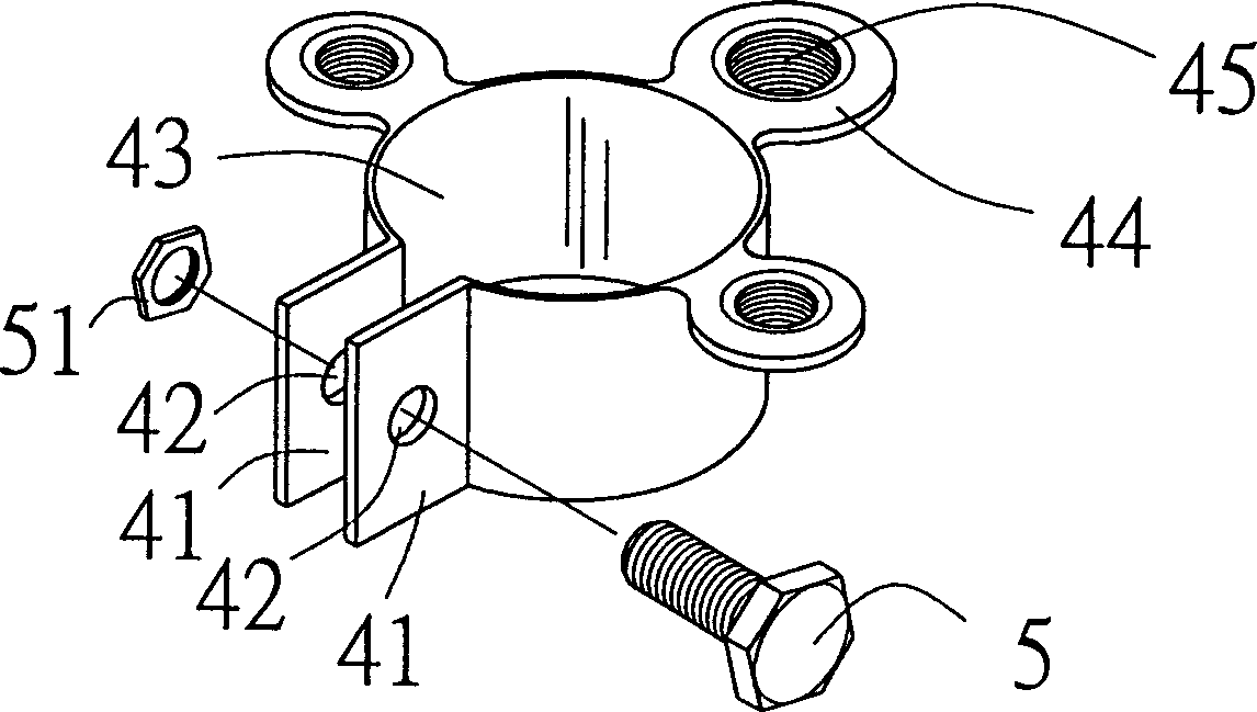
[0045] see image 3 As shown, in the present invention, a beam clamping body 4 is formed into a ring shape by an appropriate processing method, and a beam clamping guide piece 41 is extended and folded on both sides of the beam clamping body 4, and the beam clamping guide piece 41 There is a through hole 42 in the upper mirror, so that there is a gap 43 between the two sides, and the through hole 42 of the clamp guide piece 41 is penetrated by the clamp screw 5, and the clamp screw 5 is engaged with the clamp nut 51 The depth of the clamping body 4 and the displacement between the notch 43 on both sides of the clamping body 4 make the flexible clamping piece 4 produce the effect of clamping or loosening the power connector 31 of the battery 3 (see Figure 4 shown);

[0046] The upper edge of the clamp body 4 is provided with one or more wire fixing pieces (screw lock type) 44, and the wire fixing pieces (screw lock type) 44 are provided with one or more end lock screw holes 4...


PUM


Abstract

An improved bus electric level chuck is to designed at a ring shape with the two ends folded into two clamping plates with two holes and a notch in between. A screw punches through the plates engaging in the screw cap. Several screw hole plates are fixed on top of the chuck, and terminal screws lock the terminals of wires in the screw holes while the chuck in flexible phosphorus can be in smallertension. This invention increases the conductivity with more uniform distribution and arranges more conductor wires with limited space.

Description

technical field [0001] The invention relates to an automobile battery clamp with an improved structure. Background technique [0002] The traditional battery connector structure (as shown in Figure 1) is to have a screw hole 12 on the upper side of the rear section of a wiring part 11 so that the wires can be locked by screws 13, and extend on both sides of the front end of the wiring part 11. There is an elastic clip arm 14, and the elastic clip arm 14 is semicircularly curved relative to the semicircle, so that a hollow space is produced; an extension arm 15 is extended relatively parallel to the front ends of the two elastic clip arms 14, and the extension arm Each of the 15 is provided with a hole 16 for the locking screw 17 to pass through, and by means of the locking of a gasket 18 and a nut 19, the two extension arms 15 are relatively clamped, so that when the battery power supply When the joint 31 is inserted into the hollow space formed between the two elastic clam...

Claims


Application Information

Patent Timeline
IPC IPC(8): H01M2/20H01R11/11H01R11/28
CPCY02E60/12Y02E60/10
Inventor 梁世宗
Owner 梁世宗
Why Eureka
Try Eureka