Gas turbine with securing plate between blade base and disk

一种燃气涡轮机、叶片根部的技术,应用在叶片的支承元件、机械设备、发动机元件等方向,能够解决蜗轮叶轮盘构成复杂、修理麻烦、高结构开支等问题,达到可靠轴向固定、降低重量、便于加工的效果

Inactive Publication Date: 2011-10-12
SIEMENS AG
View PDF8 Cites 7 Cited by
  • Summary
  • Abstract
  • Description
  • Claims
  • Application Information

AI Technical Summary

Problems solved by technology

[0009] However, the above-described configuration of the worm wheel disk with segmentally scale-like overlapping sealing plates is rather complicated
It requires a considerable number of sealing plates, which leads to a relatively high structural outlay for the worm wheel disk and thus the entire gas turbine
In addition, repairs that may be required in the area of ​​the worm wheel disk are cumbersome due to this construction

Method used


Image

  • Gas turbine with securing plate between blade base and disk
  • Gas turbine with securing plate between blade base and disk
  • Gas turbine with securing plate between blade base and disk

Examples


Embodiment Construction

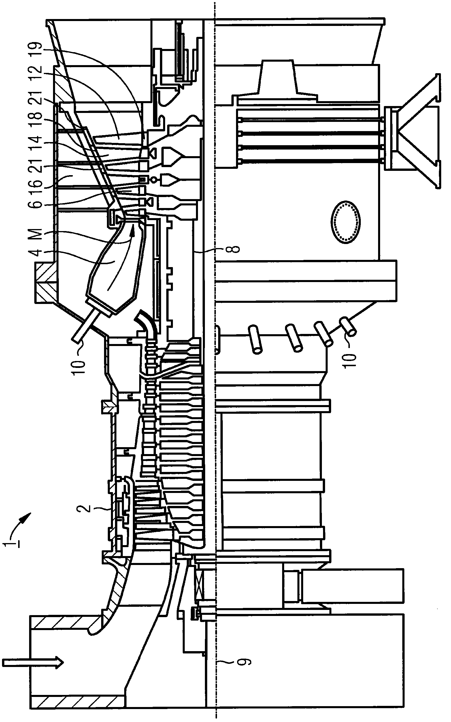
[0029] figure 1 The gas turbine 1 has a compressor 2 for combustion air, a combustion chamber 4 and a worm gear unit 6 for driving the compressor 2 and a generator or driven machine not shown. For this purpose, the worm gear unit 6 and the compressor 2 are arranged on a common worm gear rotor 8 , also referred to as a turbine rotor, to which a generator or driven machine is also connected and which is mounted rotatably about a central axis 9 . The combustion chamber 4, which is designed in the form of an annular combustion chamber, is equipped with a plurality of burners 10 for burning liquid or gaseous fuels.

[0030] The worm gear unit 6 has a plurality of rotatable rotor blades 12 connected to the worm gear rotor 8 . The rotor blades 12 are arranged in the form of a rim on the worm gear rotor 8 and thus form a plurality of rotor blade rows. The worm gear unit 6 also includes a plurality of fixed guide vanes 14 which are likewise fastened in the form of a rim to a guide va...


PUM


Abstract

A turbine rotor (8) for a gas turbine having a plurality of rotor blades (12) which are assembled into rotor blade rows and arranged on a turbine disk (36) and which each have a blade base (32) that is arranged in a rotor blade retaining groove (30) of the turbine disk extending in the axial direction, a securing plate being arranged between the respective blade base and a groove base of the rotor blade retaining groove for securing rotor blades against a displacement along the rotor blade retaining groove, said securing plate being fixed on the turbine disk by means of bevels (58), characterized in that a cooling air feed channel (48) ends in the groove base of the rotor blade retaining grooves for feeding the coolant, that the respective securing plate comprises a plurality of cooling air holes (62) for the passage of coolant, and that the respective blade base comprises two grooves (52) extending substantially azimuthally in relation to the turbine axis, and wherein the respective securing plate comprises two springs (54) which are arranged such that they can be positively connected to the grooves of the blade base for sealing.

Description

technical field [0001] The invention relates to a worm wheel rotor of a gas turbine, which has a plurality of working blades each constituting a row of working blades and arranged on a respective worm wheel disk, and the latter has working blade holding grooves respectively arranged on the worm wheel disk and extending axially One blade root in each, wherein a safety plate is set between each blade root and the groove bottom of the working blade holding groove to prevent the moving blade from moving along the working blade holding groove, and the safety plate is fixed on the worm wheel disk by means of a bent edge superior. Background technique [0002] Gas turbines are used in many fields to drive generators or driven machines. Here, the internal energy of the fuel is used to generate the rotational movement of the worm gear rotor. The fuel is combusted for this purpose in a combustion chamber, air compressed by an air compressor being supplied. The working medium at hig...

Claims


Application Information

Patent Timeline
Patent Type & Authority Applications(China)
IPC IPC(8): F01D5/30F01D5/08
CPCF01D5/087F01D5/323F05D2260/30
Inventor N·F·马丁C·席费尔P·施勒德B·范登图尔恩
Owner SIEMENS AG
Why Eureka
Try Eureka