
Lamp with at least one light-emitting diode

A technology of light-emitting diodes and light-emitting mechanisms, which is applied to semiconductor devices, light sources, and point light sources of light-emitting elements, and can solve problems such as costly structural design

Inactive Publication Date: 2011-10-12
CERAMTEC
View PDF7 Cites 1 Cited by
  • Summary
  • Abstract
  • Description
  • Claims
  • Application Information

AI Technical Summary

Problems solved by technology

In order to dissipate the heat generated by the LED, a porous ceramic material is arranged behind the metallic reflector, which requires a complex structural design

Method used


Image

  • Lamp with at least one light-emitting diode
  • Lamp with at least one light-emitting diode
  • Lamp with at least one light-emitting diode

Examples


Embodiment Construction

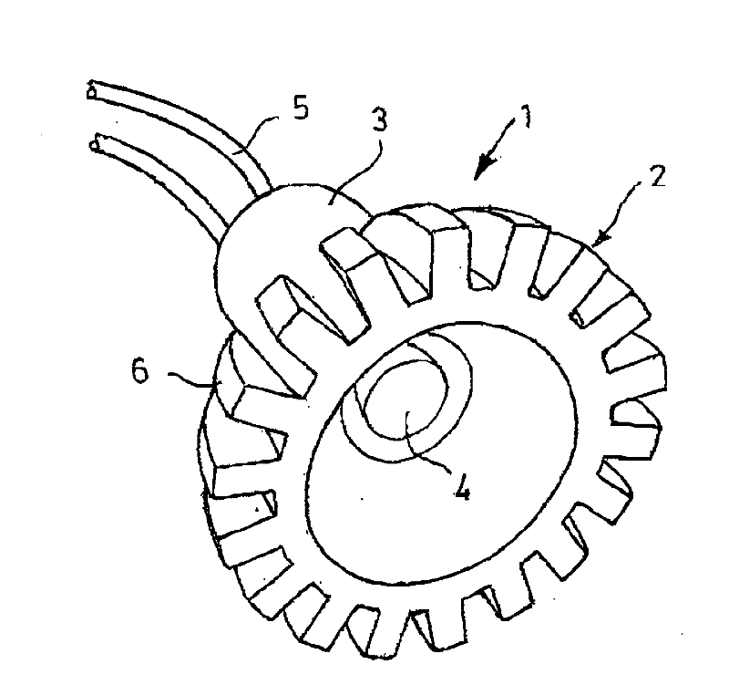
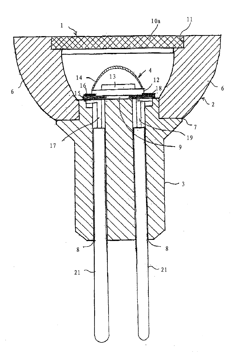
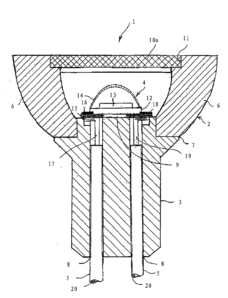
[0031] figure 1 A picture of an embodiment of a lamp 1 according to the invention is shown. The lampshade 2 and the lamp cap 3 form a lamp body and are made of white see-through ceramic material. In LEDs with low power and low heat dissipation, the material can also consist of heat-resistant plastic. In this embodiment, a light emitting diode (LED) 4 provided at the center of the lampshade 2 emits white light. Connector conductors 5 of the LED 4 protrude from the underside of the base 3 . The lampshade 2 has cooling ribs 6 evenly distributed around it, so that the shape of the lampshade 2 at its opening looks like a gear. Especially in the case of high-power LEDs, cooling ribs are advantageous in order to dissipate the heat generated to the surrounding air. The cross-section of the cooling ribs can also take any other possible shape, for example semi-circular or semi-elliptical. In LEDs with low heat loss, the lampshade can also be smooth. The shade can likewise have dif...


PUM

PropertyMeasurementUnit
Breaking strengthaaaaaaaaaa

Abstract

With consideration to energy savings, conventional illumination elements are being replaced by LEDs to an increasing degree. However, the higher the increase in light output, the higher the increase in losses due to radiated heat. To optimally dissipate the incident heat, it is proposed that in a lamp (1, 30) comprising at least one LED (Light Emitting Diode) (4, 34) as a illumination means, comprising a lamp body with a shield (2, 32, 32a) surrounding the LED and a socket (3, 33, 61) holding the LED, the lamp body of the lamp (1, 30) should be made entirely of a ceramic material.

Description

technical field [0001] The invention relates to a lamp having at least one light emitting diode (LED=Light Emitting Diode), which is arranged on a base and is surrounded by a cap-like body as heat sink. The lamp base and lampshade can consist of a ceramic material. Background technique [0002] With a view to saving energy, conventional lighting bodies are increasingly being replaced by LEDs. However, the higher the light output increases, the greater the loss due to radiated heat increases. This is especially the case in high power LEDs. For example, an LED with an input power of 4 watts at 1 ampere emits 1.2 watts of radiant energy as light, and the heat loss that must be dissipated is 2.8 watts. A so-called high-power solid-state lighting device is known from DE 112006001536 T5. In order to dissipate the heat generated by the LEDs, a porous ceramic material is arranged behind the metallic reflector, which requires a complex structural design. Contents of the inventi...

Claims


Application Information

Patent Timeline
IPC IPC(8): F21V7/22F21K99/00F21Y101/02
CPCF21V27/02F21V23/002F21K9/233F21Y2115/10F21K9/237F21V15/01F21V29/00
Inventor M.赫默勒
Owner CERAMTEC
Learn More