
Bonding apparatus and bonding method

A technology of bonding device and pushing device, which is applied in optics, instruments, nonlinear optics, etc., to achieve the effect of preventing the dislocation of workpieces

Inactive Publication Date: 2014-07-30
SHIBAURA MECHATRONICS CORP
View PDF3 Cites 0 Cited by
  • Summary
  • Abstract
  • Description
  • Claims
  • Application Information

AI Technical Summary

Problems solved by technology

However, in the case of the cover panel pasted on the liquid crystal template, since it is also an exterior decoration part of the final product, it is often printed except for the viewing window part, and ultraviolet rays cannot be transmitted. Therefore, it cannot harden temporarily

Method used


Image

  • Bonding apparatus and bonding method
  • Bonding apparatus and bonding method
  • Bonding apparatus and bonding method

Examples


Embodiment Construction

[0033] Next, embodiments of the present invention (hereinafter referred to as embodiments) will be described in detail with reference to the drawings.

[0034] [A. Structure]

[0035] [1. Overall structure]

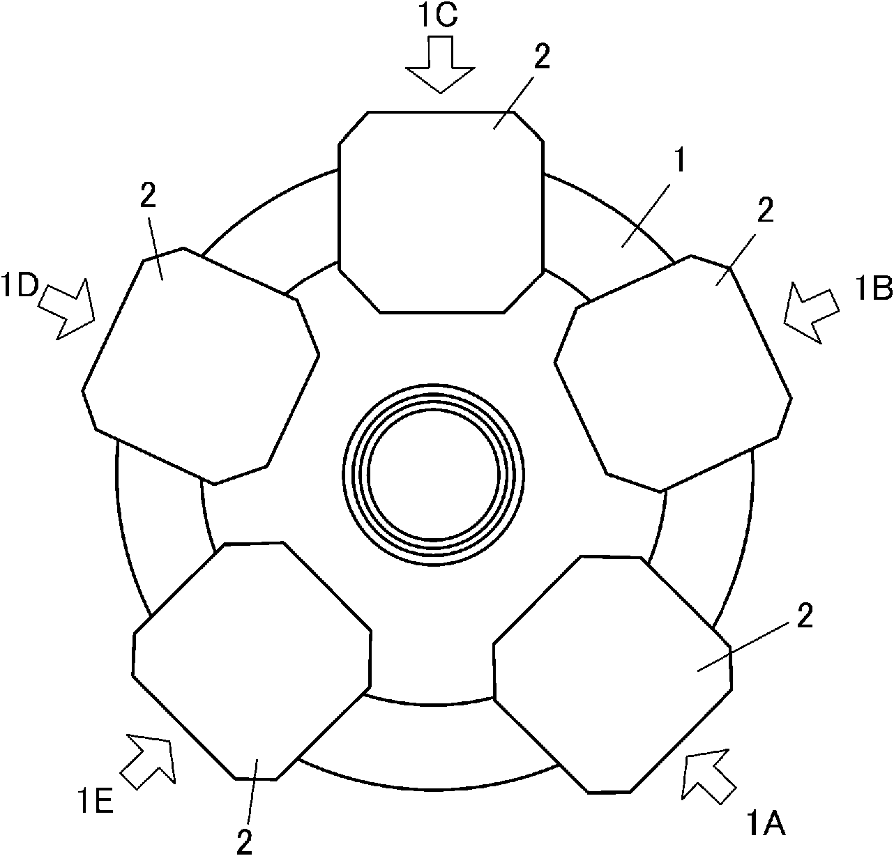
[0036] First, the overall structure of the bonding apparatus of this embodiment (hereinafter referred to as the apparatus) will be described. This device is figure 1 As shown in , five holding devices 2 are mounted on the turntable 1 . The turntable 1 is configured to be intermittently rotated by an index mechanism in accordance with the insertion and removal position 1A, the adhesive material preparation position 1B, the positioning position 1C, the vacuum bonding position 1D, and the curing position 1E.

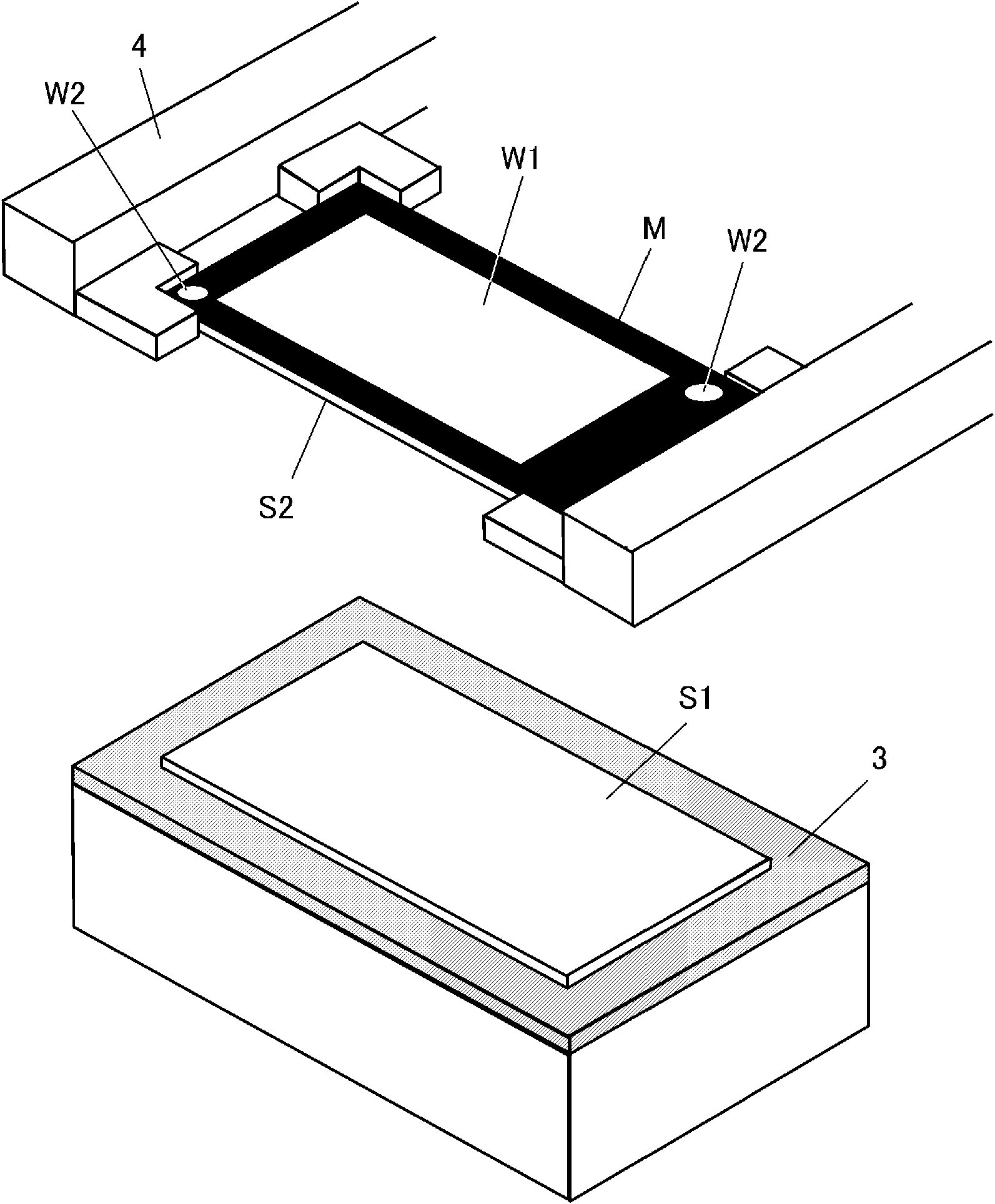
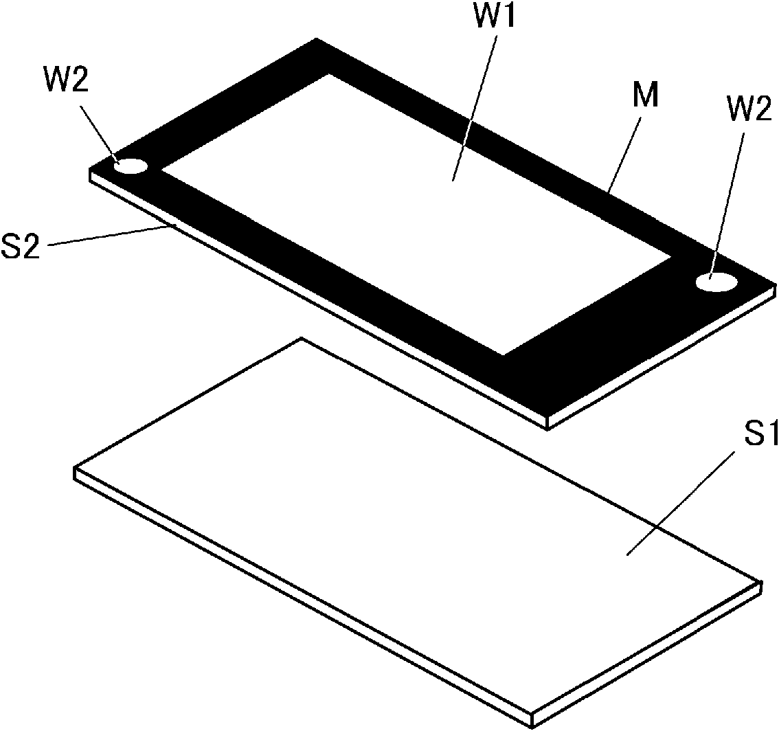
[0037] holding device 2 such as figure 2 As shown, it is a device that holds the workpiece S1 mounted on the placement unit 3 and the workpiece S2 held by the holding unit 4 facing each other up and down. In this embodiment, a liquid crystal template is used as t...


PUM


Abstract

The present invention provides a bonding device and a bonding method capable of preventing misalignment of workpieces in a short time with a simple device without reducing optical quality and manufacturing efficiency. In the present invention, it is a bonding device that sandwiches an ultraviolet curable resin (T) and bonds a pair of workpieces (S1, S2). The cover panel with the window part (W1), the shielding part (M) with low transmittance of visible light, and the hardening window part (W2) that allows ultraviolet (UV) to pass through has the function of pressing the workpiece (S2) to the workpiece (S1 ) a pressing device (5) for bonding, and a local irradiation device (54, 55) for irradiating ultraviolet (UV) to the hardening window (W2) in the workpiece bonded by the pressing device (5).

Description

technical field [0001] The present invention relates to a bonding device and a bonding method which have improved the technology of bonding workpieces such as liquid crystal templates and cover panels. Background technique [0002] Generally, a liquid crystal panel is formed by laminating a liquid crystal template, a touch panel for operation, a cover panel (protective panel), and the like. These liquid crystal templates, touch panels, cover panels, etc. (hereinafter referred to as workpieces) are assembled on the frame of the liquid crystal template, and in order to avoid contact with the liquid crystal glass due to the deformation of the touch panel and cover panel, a space is formed between them. [0003] However, if a layer of air enters between the workpieces, the visibility of the display surface will decrease due to reflection of natural light. In order to cope with this situation, bonding is carried out by forming a layer that fills the space between the workpieces ...

Claims


Application Information

Patent Timeline
Patent Type & Authority Patents(China)
IPC IPC(8): G02F1/13G02F1/1333G02F1/1335G11B7/26
CPCG02F1/133308G11B7/26G02F1/133G02F1/1303G02F1/13G02F1/1333
Inventor 横田典之
Owner SHIBAURA MECHATRONICS CORP
Learn More