
Fly killing device

A technology for killing and flying insects, which is applied in the direction of trapping or killing insects, applications, animal husbandry, etc., can solve the problems of difficult collection and management of pests, inability to carry out diverse hunting, and narrow application range, so as to improve life Effects of environmental quality, changing the concept of pest control, and good killing effect

Active Publication Date: 2011-10-19
徐州伊泽瑞智智能设备有限公司
View PDF8 Cites 2 Cited by
  • Summary
  • Abstract
  • Description
  • Claims
  • Application Information

AI Technical Summary

Problems solved by technology

Existing products for catching and killing mosquitoes, flies and other flying pests mainly use methods such as glue sticking, spraying medicine, baiting, light lure, electric shock, etc. These methods are less versatile for killing mosquitoes, flies and other flying insects. Strong regionality, narrow application range, single performance, strong pertinence, can not carry out diverse hunting, and it is not easy to collect and manage the killed pests

Method used


Image

  • Fly killing device
  • Fly killing device
  • Fly killing device

Examples


Embodiment 1

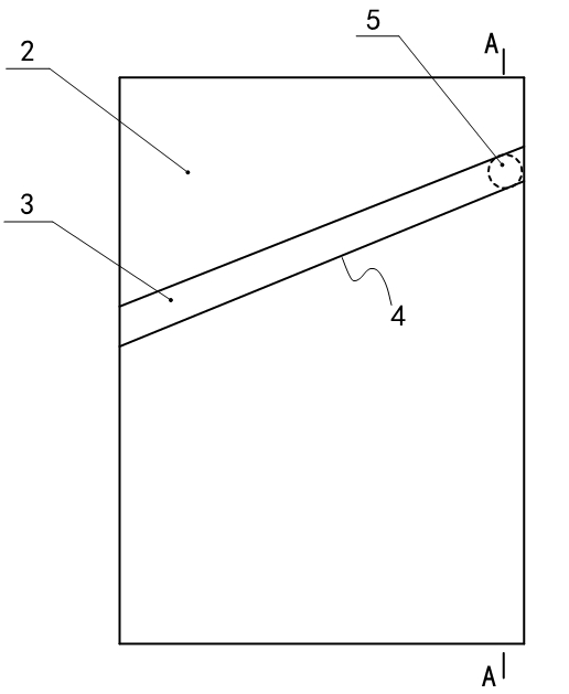
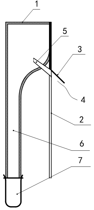
[0023] Embodiment one: the specific embodiment of the flying insect killing device of the present invention is as figure 1 , figure 2 As shown, it has a storage box 1 that is mainly surrounded by gauze, and one side of the storage box 1 is provided with an end panel 2, and the upper part of the end panel 2 is integrally fixed on the side wall of the storage box 1. The lower part extends vertically downwards. On the outer end surface of the end panel 2 away from the storage box, a bar-shaped eaves 3 made of light-transmitting and / or air-permeable materials is fixed. In this embodiment, the end panel 2 is made of glass or gauze and other light-transmitting and air-permeable materials, as an optimization scheme of this embodiment, it is provided with a shield made of opaque material on the end panel 2 above the eaves 3, so that the top of the eaves 3 Opaque, so that the light transmission and air permeability of the end panel 2 below the eaves 3 are more prominent, and the misl...

Embodiment 2

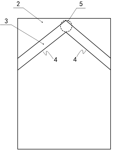
[0025] Embodiment two: if image 3 As shown, the difference between the second embodiment and the first embodiment is that two retaining eaves 3 are arranged on the outer end surface of the end panel 2 away from the storage box, and the two retaining eaves 3 are obliquely directed from both sides of the end panel 2 respectively. It extends upwards and intersects the middle of the end panel 2 to form an upwardly convex inverted V-shaped structure, and the connecting channel 5 is connected to the highest point where the middles of the two retaining eaves 3 intersect.

Embodiment 3

[0026] Embodiment three: as Figure 4 As shown, the difference between the third embodiment and the first embodiment is that two retaining eaves 3 are arranged on the outer end surface of the end panel 2 away from the storage box, and the two retaining eaves 3 are obliquely directed from both sides of the end panel 2 respectively. The lower extension intersects in the middle of the end panel 2 to form a V-shaped structure. The highest points of the two retaining eaves 3 located on both sides of the end panel 2 communicate with the storage box 1 through correspondingly connected connecting channels 5 .


PUM


Abstract

The invention discloses a fly killing device which comprises a fly attracting device, a storage box and a connecting passage connected between the fly attracting device and the storage box, wherein the fly attracting device comprises an end panel arranged vertically, and the end panel is provided with an oblique fly attracting passage through a fixedly arranged blocking edge; and the inlet end ofthe connecting passage is communicated with the fly attracting passage, and the outlet end of the connecting passage is obliquely upwards extended to the middle part of the storage box. The fly killing device does not need labor management and has a simple structure; the device makes full use of the characteristic that the fly flies upwards in a euphotic or air-permeable barrier to seek a barrierbreakthrough port to misguide the fly, so that the fly enters the storage box and naturally dies due to hunger and dehydration, and killing and storing processes are automatically completed; and because electricity, agent, sticking and attraction of food or light are not used in the killing process, the device has the characteristics of low carbon, energy conservation, environmental friendliness and high efficiency.

Description

technical field [0001] The invention relates to a killing device for killing flying insects such as mosquitoes and flies. Background technique [0002] Livestock and poultry farming in rural areas are deeply affected by flying pests such as mosquitoes, flies, wild peaks, and moths. Existing products for catching and killing mosquitoes, flies and other flying pests mainly use methods such as glue sticking, spraying medicine, baiting, light lure, electric shock, etc. These methods are less versatile for killing mosquitoes, flies and other flying insects. Strong regionality, narrow application range, single performance, and strong pertinence, it cannot be used for diverse hunting, and it is not easy to collect and manage the killed pests. Contents of the invention [0003] The object of the present invention is to provide a flying insect killing device capable of carrying out diverse hunting and killing. [0004] The technical solution of the present invention is: a device ...

Claims


Application Information

Patent Timeline
IPC IPC(8): A01M1/10
Inventor 韩启峰
Owner 徐州伊泽瑞智智能设备有限公司
Learn More